4 En Part names and functions
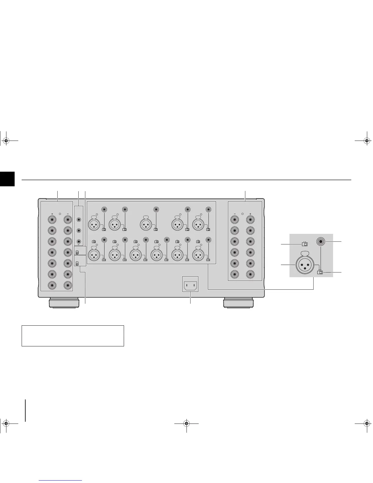
Rear panel
1 SPEAKERS terminals
For connecting to speakers (p.7).
2 TRIGGER jacks
For connecting to devices that support the trigger function (p.9).
3 AUTO POWER STANDBY switch
Enables/disables the auto-standby function (p.8).
4 IMPEDANCE SELECTOR
Changes the unit’s speaker impedance setting depending
on the speakers connected (p.7).
5 AC IN jack
For connecting the supplied power cable (p.8).
6 CH. SELECTOR
(CH.3, CH.4 and CH.6 only)
Selects the audio source input to the CH.3, CH.4 or CH.6
amplifier when applying a bi-amp connection (p.10) or a
multi-speaker connection (p.10).
Caution
• Remove the unit’s power cable from an AC wall outlet before
making any connections or operating the switches and/or
selectors.
MX-A5000_om_UCTKABGLVF.book Page 4 Thursday, April 4, 2013 5:28 PM