13
PSR-E343/PSR-E344/YPT-340
4. PN Circuit Board, AM Circuit Board, MVR
Circuit Board
4-1 Remove the lower case assembly. (See procedure 1)
4-2 MVR Circuit Board (Time required: About 3 minutes)
4-2-1 Remove the knob from the control panel surface.
(Fig.1, Fig.4)
4-2-2 Remove the three (3) screws marked [380B]. The MVR
circuit board can then be removed. (Fig.2)
4-3 AM Circuit Board (includes DC-IN)
(Time required: About 4 minutes)
4-3-1 Remove the MVR circuit board. (See procedure 4-2)
4-3-2 Remove the seventeen (17) screws marked [380C]. The
AM circuit board can then be removed. (Fig.2)
4-4 PN circuit board (Time required: About 3 minutes)
4-4-1 Remove the thirteen (13) screws marked [380D]. The PN
circuit board can then be removed. (Fig.2)
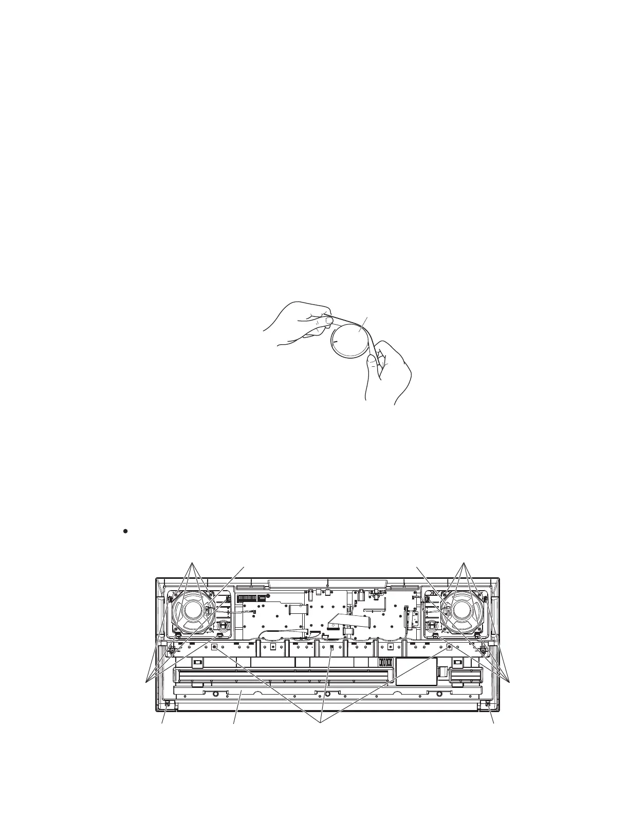
5. Speaker (Time required: About 3 minutes)
5-1 Remove the lower case assembly. (See procedure 1)
5-2 Remove the four (4) screws marked [370]. The speaker
can then be removed. (Fig.5)
* The right and left speakers can be removed in the
same manner.
4. PN シート、AM シート、MVR シート
4-1 下ケース Ass'y を外します。(1 項参照)
4-2 MVR シート(所要時間:約 3 分)
4-2-1 コントロールパネル面から V ツマミを外します。
(図 1、図 4)
4-2-2 [380B]のネジ 3 本を外して、MVR シートを外し
ます。(図 2)
4-3 AM シート(DC-IN 含む)(所要時間:約 4 分)
4-3-1 MVR シートを外します。(4-2 項参照)
4-3-2 [380C]のネジ 17 本を外して、AM シートを外し
ます。(図 2)
4-4 PN シート(所要時間:約 3 分)
4-4-1 [380D]のネジ 13 本を外して、PN シートを外しま
す。(図 2)
5. スピーカ(所要時間 :約3分)
5-1 下ケース Ass'y を外します。(1 項参照)
5-2 [370]のネジ 4 本を外して、スピーカを外します。
(図5)
※ 左右のスピーカは同じように外せます。
KNOB
(Vツマミ)
Fig.5(図 5)
63($.(5
(スピーカ)
/2:(5.(<%('$66(0%/<
(下ケース鍵盤Ass'y)
63($.(5
(スピーカ)
>@
>@
>@ >@
>@
>$@ >$@
%RWWRPYLHZ(下から見た図)
Fig.4(図 4)