16
PSR-E343/PSR-E344/YPT-340
8-5
シート 61L
8-5-1 C1〜B3の白鍵・黒鍵を外します。
(図 6、8-3項参照)
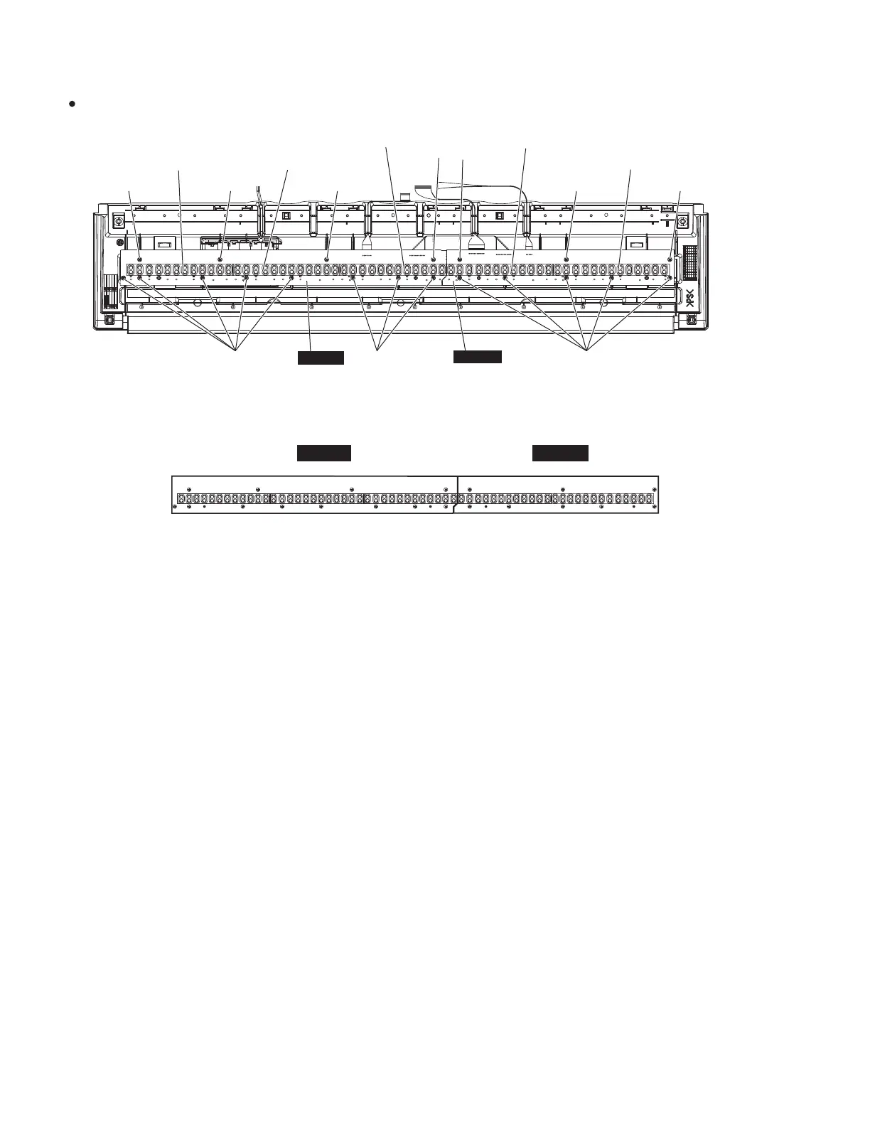
8-5-2 [100C]のネジ 4本と [110A]のネジ 8本を外して、
シート 61Lを外します。(図 7)
※ シート 61Lを取り付けるときは、図 8のシート
61L図の番号 1〜12の順にネジを締めてくださ
い。(図 8)
8-6
シート 61H
8-6-1 C4〜C6の白鍵・黒鍵を外します。
(図 6、8-3項参照)
8-6-2 [100D]のネジ 3本と [110B]のネジ 5本を外して、
シート 61Hを外します。(図 7)
※ シート 61Hを取り付けるときは、図 8のシート
61H 図の番号 1〜8の順にネジを締めてください。
(図8)
8-5
Circuit Board 61L-MK
8-5-1 Remove the white and black keys from C1 to B3.
(See Fig.6 and Procedure 8-3.)
8-5-2 Remove the four (4) screws marked [100C] and
eight (8) screws marked [110A]. The circuit board
61L-MK can then be removed. (Fig.7)
* When installing the circuit board 61L-MK, tighten
the screws 1 through 12 in numerical order as
shown in the fi gure “61L-MK” in Fig.8. (Fig.8)
8-6 Circuit Board 61H-MK
8-6-1 Remove the white and black keys from C4 to C6.
(See Fig.6 and Procedure 8-3.)
8-6-2 Remove the three (3) screws marked [100D] and
fi ve (5) screws marked [110B]. The circuit board
61H-MK can then be removed. (Fig.7)
* When installing the circuit board 61H-MK, tighten
the screws 1 through 8 in numerical order as
shown in the fi gure “61H-MK” in Fig.8. (Fig.8)
Fig.8(図 8)
2118765432 345
8762111019
61L-MK
61H-MK
>&@
>$@
>&@ >&@
>&@
>'@
>'@ >'@
>$@ >%@
58%%(5&217$&7
(接点ゴム)
58%%(5&217$&7
(接点ゴム)
58%%(5&217$&7
(接点ゴム)
58%%(5&217$&7
(接点ゴム)
58%%(5&217$&7
(接点ゴム)
/0.
+0.
7RSYLHZ(上から見た図)
Fig.7(図 7)