12345678
A
B
C
D
E
F
20
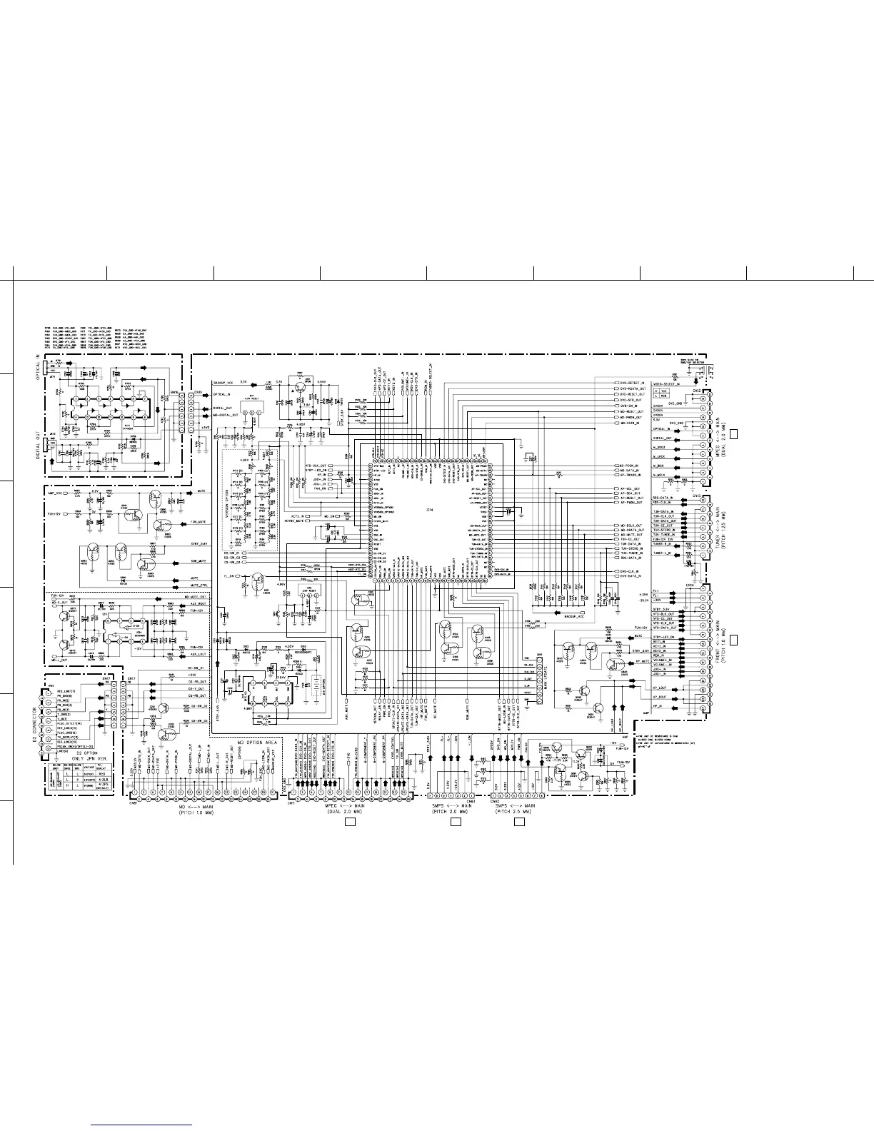
RDX-E700/NX-E700
■ SCHEMATIC DIAGRAM (MAIN 1/2 (Microprocessor))
TO MPEG 1/2 CN36
Page 18 B-7
TO FRONT CN14
Page 22 B-1
TO POWER CN92
Page 23 B-7
TO POWER CN93
Page 23 D-7
TO MPEG BACK END CN35
Page 19 A-8
TO AM/FM TUNER
ST92F124V1
FLASH
Mircroprocessor
MAIN (2)
MAIN (1)
MAIN (3)
* Components having special characteristics are marked
Z
and must be replaced with parts having specifications equal
to those originally installed.
* Schematic diagram is subject to change without notice.
* Z印のある部品は、安全性確保部品を示しています。部品の交換が必要な場
合、パーツリストに記載されている部品を使用してください。
* 本回路図は、標準回路図です。改良のため予告なく変更することがございま
す。
FOR INFORMATION ONLY (NO REPLACEMENT COMPONENT PARTS WILL BE AVAILABLE)