12345678
A
B
C
D
E
F
21
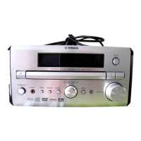
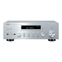
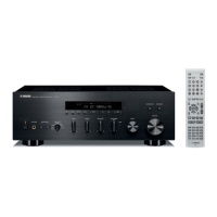
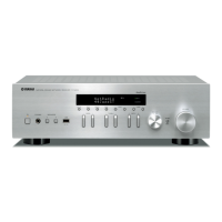
RDX-E700/NX-E700
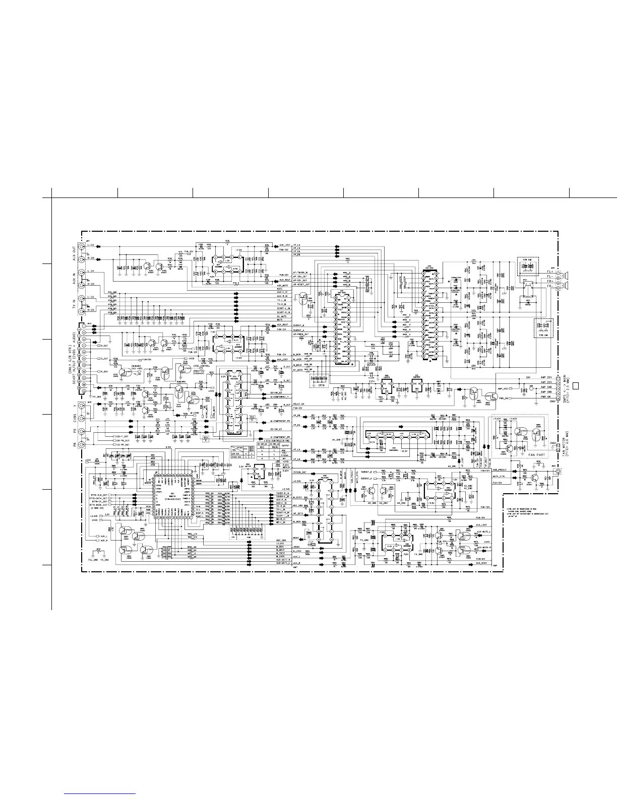
■ SCHEMATIC DIAGRAM (MAIN 2/2 (FUNCTION & AMP))
TO POWER CN91
Page 23 C-7
MAIN (1)
* Components having special characteris-
tics are marked
Z
and must be replaced
with parts having specifications equal to
those originally installed.
* Schematic diagram is subject to change
without notice.
* Z 印のある部品は、安全性確保部品を示していま
す。部品の交換が必要な場合、パーツリストに記載
されている部品を使用してください。
* 本回路図は、標準回路図です。改良のため予告なく
変更することがございます。
FOR INFORMATION ONLY (NO REPLACEMENT COMPONENT PARTS WILL BE AVAILABLE)