Do you have a question about the Yamaha S80 and is the answer not in the manual?
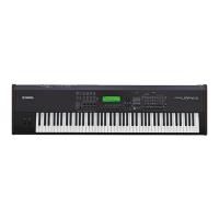
| Type | Synthesizer |
|---|---|
| Sound Engine | AWM2 |
| MIDI | In/Out/Thru |
| Inputs | Foot controller, Foot switch, Breath controller |
| Multitimbral | 16 parts |
| Year Released | 1999 |
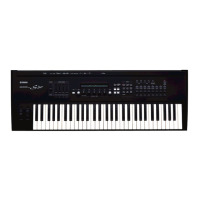
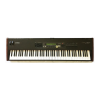
| Keyboard | 88 keys, weighted action |
| Polyphony | 64 notes |
| Effects | Reverb, Chorus |
| Outputs | L/Mono, R |
| User Patches | 128 User Voices |
| Display | 240 x 64 dot graphic LCD |
Disclaimer regarding service procedures and authorization requirements.
Guidelines for safe handling and replacement of the internal lithium battery.
Notice about lead and other chemical content in product components.
Steps to remove the control panel, PN, RV boards, and power supply.
Procedures for removing SM, SV, JK, DM, Wheel, and PC boards.
Detailed steps for disassembling and reassembling the keyboard keys and hammers.
Detailed pin assignments for CPU (PKS) and DAC ICs.
Pin assignments for DDE1 (JG710069) and other ICs.
Block diagrams for logic gates, demultiplexers, buffers, and transceivers.
Block diagrams for amplifier, receiver, inverter, and flip-flop ICs.
Instructions for entering tests and testing RAM, WAVE ROM, LCD, and Panel controls.
Tests for Keyboard, Knobs, Sliders, Controllers, Foot Controls, and Breath Controller.
Tests for Card, MIDI, HOST, mLAN, Factory Settings, and system operations/shortcuts.