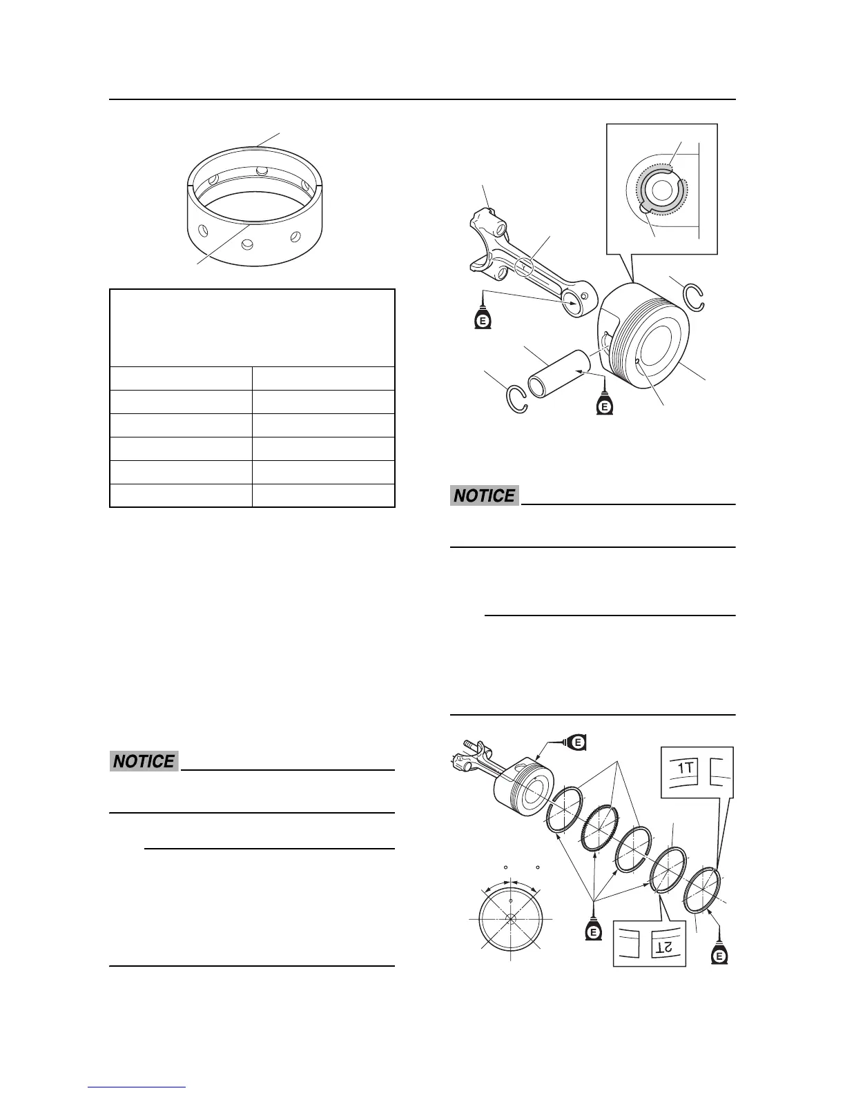
Crankcase, connecting rod, and piston
5-84
“J1” crankcase journal size number “5”
“J1” crankshaft journal size number “2”
5 - 2 = 3
Select the size “3”, “Blue” crankshaft bear-
ing.
Connecting rod and piston
installation
1. Assemble the connecting rod “1”, piston
“2”, piston pin “3”, and new piston pin clips
“4”.
Do not reuse a piston pin clip, always re-
place it with a new one.
• When installing the connecting rod to the pis-
ton, make sure that the “Y” mark “a” on the
connecting rod faces toward the front mark
“b” on the piston crown.
• Do not allow the piston pin clip ends to align
with the piston pin slot “c”.
2. Install the oil ring “1”, 2nd ring “2”, and top
ring “3”.
Do not scratch the pistons or break the pis-
ton rings.
3. Offset the piston ring end gaps.
• Make sure to install the piston rings so that
the “1T” mark on the top ring “3” and the “2T”
mark on the 2nd ring “2” face up.
• After installing the piston rings, make sure
that they move smoothly.
4. Clean the connecting rod bearings “1” and
connecting rod big end.
Calculation formula:
Crankshaft bearing size number = crank-
case journal size number - crankshaft jour-
nal size number
Bearing size number Bearing color
1Brown
2Black
3Blue
4Green
5Yellow
#1
#2
#2
#1
5454
#3
#3
#4
#4
#5
#5
1
2
3
 Loading...