Control system
7-26
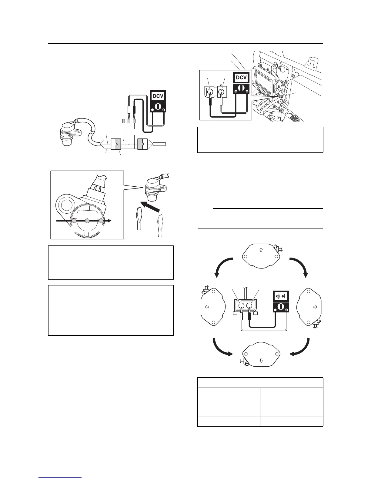
5. Supply power to the ECM, and then mea-
sure the output voltage when a screw-
driver is passed under the cam position
sensor in direction “A”. Replace the cam
position sensor if out of specification.
6. Disconnect the special service tool.
7. Install the cam position sensor. See “Cylin-
der head cover” (5-31).
Slant detection switch check
1. Disconnect the slant detection switch cou-
pler “a”.
2. Supply power to the ECM, and then mea-
sure the input voltage at the slant detection
switch coupler (wire harness end). Check
the wire harness if out of specification.
3. Remove the slant detection switch. See
“Electrical box” (5-19).
4. Check the slant detection switch for conti-
nuity. Replace if out of specification.
Make sure to turn the switch over to both the
left and right.
5. Install the slant detection switch. See
“Electrical box” (5-19).
Test harness (3 pins) “1”
90890-06877
Test harness (3 pins) “1”
YB-06877
Output voltage (position a, c)
More than 4.8 V
Output voltage (position b)
Less than 0.8 V
Green/Orange (G/O)–Black/Orange
(B/O)
Input voltage
4.75–5.25 V
Blue/Black (L/B)–Black/Orange (B/O)
Slant detection switch continuity
Position
Blue/Black (L/B)–
Black/Orange (B/O)
Normal position “A” No continuity
Overturned “B” Continuity

 Loading...