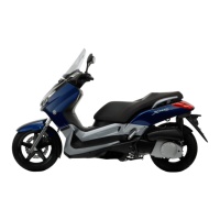
Do you have a question about the Yamaha XP500 2001 and is the answer not in the manual?
Provides crucial guidelines for maintenance, parts, and safety procedures.
Lists overall dimensions, weight, and load capacity of the scooter.
Details engine type, displacement, bore, stroke, compression, and fluid capacities.
Covers frame, wheel, tire, and brake system specifications.
Outlines recommended service schedule based on odometer readings and time.
Covers valve clearance, carburetor sync, idling speed, and oil level checks.
Details removal, disassembly, checking, assembly, and balancing of the front wheel assembly.
Explains brake pad replacement, master cylinder checks, and caliper service procedures.
Covers removal, checking, and installation of camshafts, sprockets, and timing chain.
Details removal, checking, and installation of the cylinder head assembly.
Explains assembly and disassembly of crankcase, crankshaft, connecting rods, and bearings.
Covers radiator and oil cooler removal, checking, and installation procedures.
Explains thermostat checking and installation procedures.
Details water pump removal, disassembly, checking, and assembly.
Covers carburetor removal, disassembly, checking, assembly, and installation.
Explains the air induction system, air cutoff valve, and diagrams.
Details ignition system circuit diagram, troubleshooting, and component checks.
Covers starting system circuit diagram, operation, troubleshooting, and starter motor service.
Covers lighting system circuit diagram and troubleshooting for various lights.
Details signal system circuit diagram and troubleshooting for horn, turn signals, and lights.
Lists potential causes for engine starting issues across various systems.
Details issues related to disc brakes, hydraulic systems, and brake fluid.
| Displacement | 499 cc |
|---|---|
| Fuel System | Fuel injection |
| Ignition System | TCI |
| Front Suspension | Telescopic fork |
| Rear Suspension | Swingarm |
| Front Brake | Single disc |
| Rear Brake | Single disc |
| Front Tire | 120/70-14 |
| Rear Tire | 150/70-13 |
| Wheelbase | 1, 590 mm |
| Bore x Stroke | 66.0 mm x 73.0 mm |
| Transmission | Automatic |

