–11–
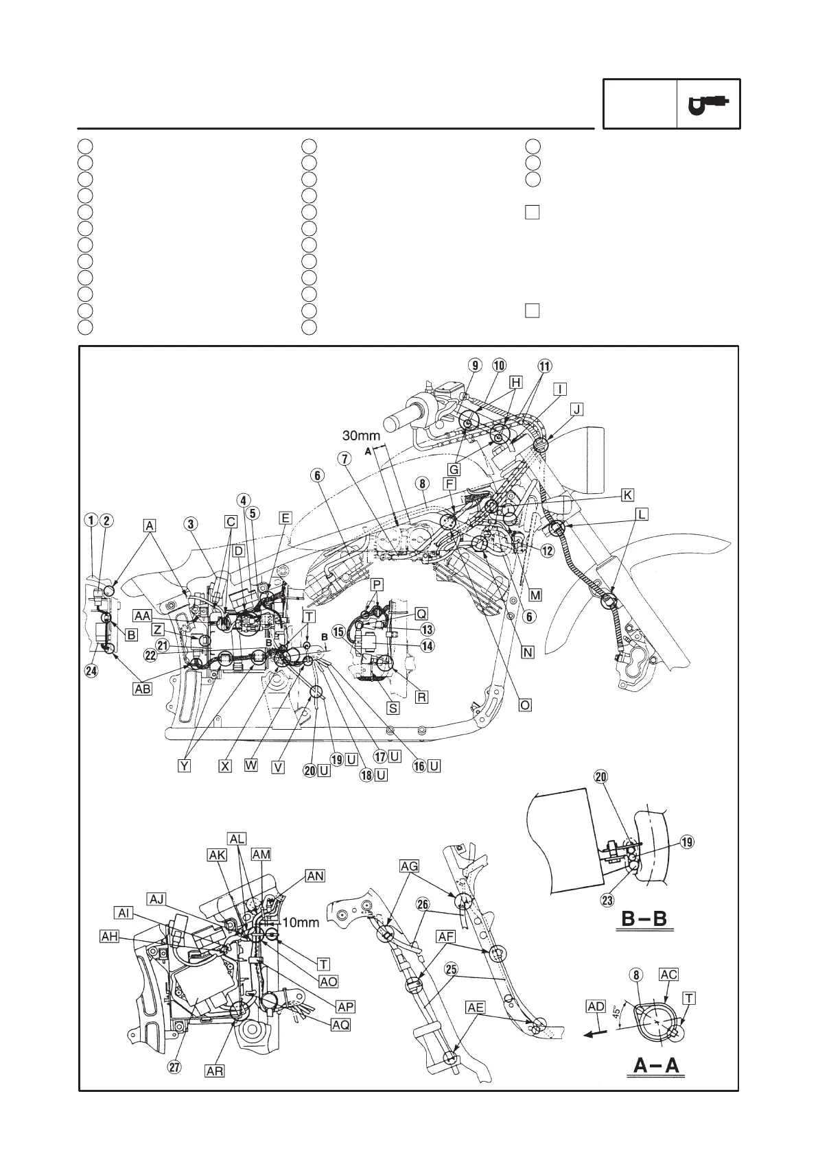
25 Fuel tank breather hose
26 Speedometer cable
27 Ignitor unit
A Pass the tail/brake light lead
between the frame bracket and
battery box. Position the mud
guard the between the edge of
the frame bracket and the
tail/brake light lead.
B Fasten the dimmer switch lead
with a clamp.
13 Flasher light relay
14 Starter relay
15 Carburetor heater relay
16 Neutral switch lead
17 Pickup coil lead
18 A.C. magneto lead
19 Battery negative (–) lead
20 Starter motor lead
21 Battery cover
22 Battery
23 Wire harness
24 Starting circuit cut-off relay
1 Frame bracket
2 Dimmer switch
3 Self-canceling turn signal relay
4 Fuse box
5 Battery positive (+) lead
6 Spark plug lead
7 Vacuum chamber air bent hose
8 Starter cable
9 Right handlebar switch lead
10 Brake hose
11 Throttle cables
12 Thermo switch lead
CABLE ROUTING
SPEC