–12–
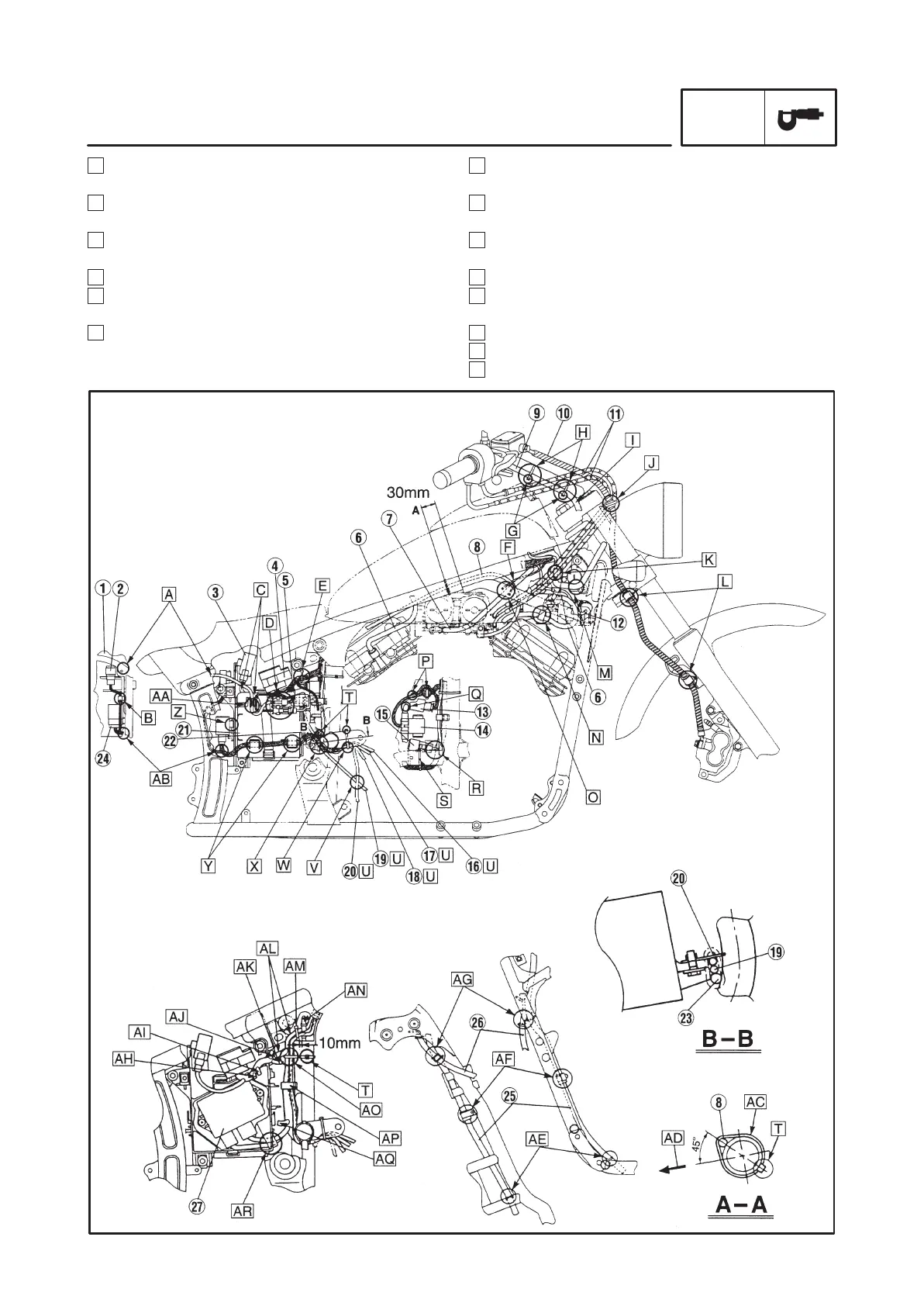
I Pass the right handlebar switch lead behind the
upper bracket.
J Fasten the brake hose grommet with a brake hose
holder.
K Place the left handlebar switch coupler on the side
of the main switch.
L Fasten the brake hose with a brake hose holder.
M Pass the left handlebar switch lead under the main
switch.
N Fasten the spark plug lead with a metal clamp.
O Pass the ignition coil lead inside of the starter cable.
P Fasten the fuse box lead with a plastic locking tie.
C Fasten the self-canceling turn signal relay lead and
battery positive (+) lead with a battery band.
D Fasten the tail/brake light lead coupler and battery
negative (–) lead coupler with a clamp.
E Fasten the starter relay lead and fuse box lead with
a plastic locking tie.
F To the ignition coil.
G The end of the plastic locking tie should face
towards the under the handlebar.
H Fasten the right handlebar switch lead with a plastic
locking tie.
CABLE ROUTING
SPEC