2. Installation
2.2 Full-submerged type
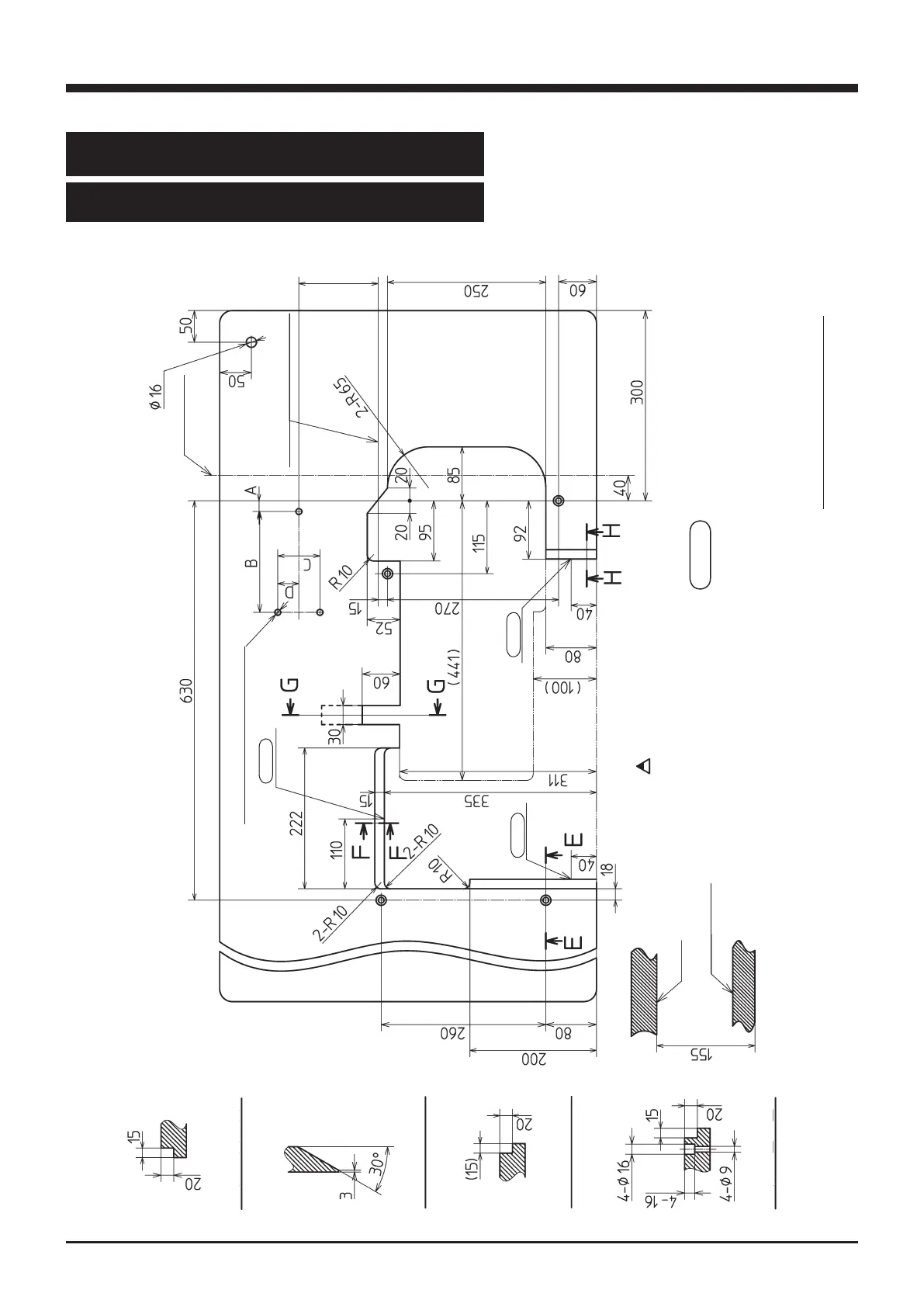
2.2.1 Table cutting diagram
Fig. 2-5
Refer to the instruction manual of the motor
for dimensions A, B, C, and D.
center of pulley
Table dimensions: 1200×595×40
Operator
3- φ 9.5 installing hole of motor
Section H - H
Section G - G
Section F - F
Section E - E
magnet
magnet
magnet
Table
Supporting board
Note: 125 is reference dimension which differ by kindes of the motor.
“155” in the above gure is the distance to the bottom of the supporting board
so it must be set to the dimension where there will be no interference between
the motor control panel and the bottom and back end of the supporting board.
Note: Position of the rear end
of supporting board
Note: (125)
Magnet : Shown in the diagram are the
reference positions where the magnet
catches are to be installed.
 Loading...