Home
Yanmar
Engine
4JH3BE
Page 128 (1-5 Sectional view)
Yanmar 4JH3BE - 1-5 Sectional view
284 pages
Manual
Save Page as PDF
To Next Page
To Next Page
To Previous Page
To Previous Page
Loading...
Chapter
7
Reduction
and
Reversing
Gear
~l.:...
,::C,:;:;on:.:;s:;;.:t;.;:;,,r.::,uc,:;;,;t:;.:,;io~n,;.._
___________________________
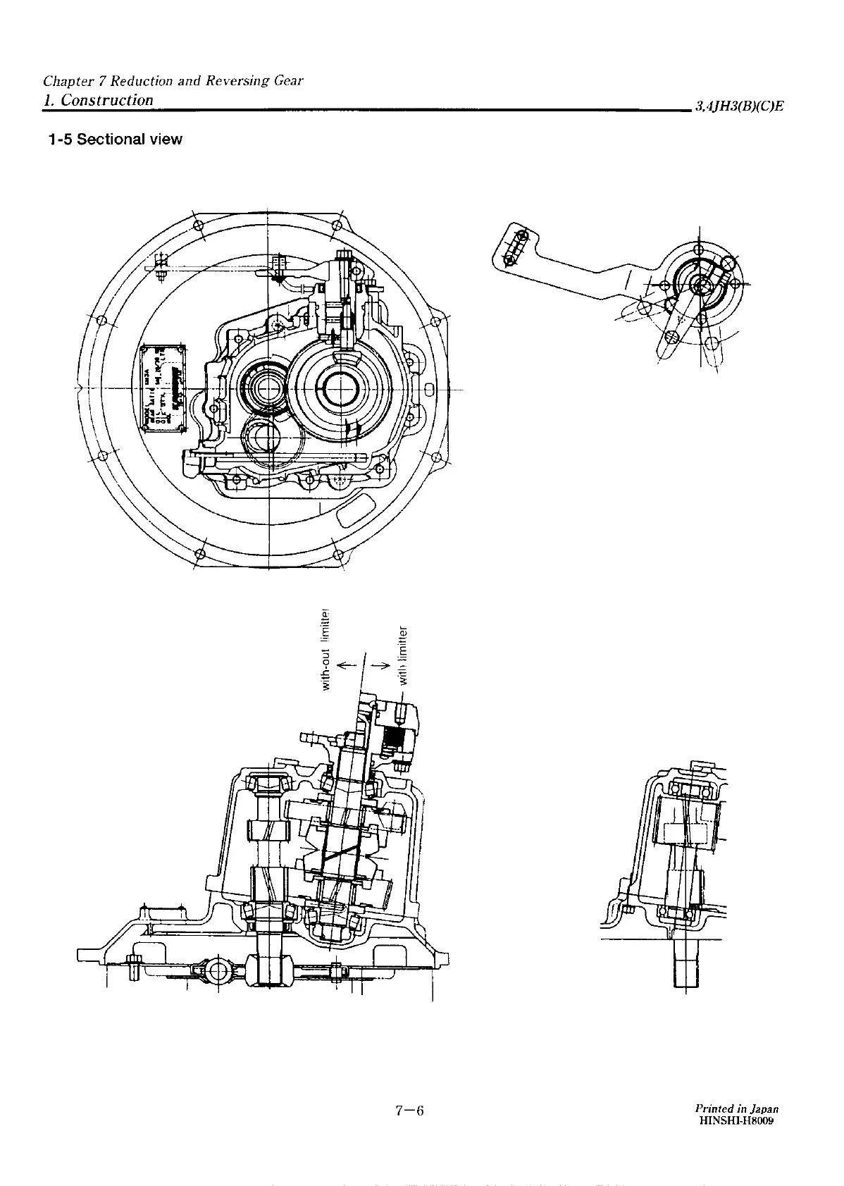
3,4JH3(B)(C)E
1-5
Sectional
view
7-6
Printed
in
Japan
HINSHI-H8009
127
129
Table of Contents
Main Page
COVER
1
FOREWORD
2
INDEX
3
Chapter 1 GENERAL
4
1. Exterior Views
5
1-1 3JH3E
5
1-2 4JH3E
6
2. Specifications
7
2-1 3JHE,3JH3BE,3JH3CE
7
2-2 4JH3E,4JH3BE,4JH3CE
8
2-3 Sales condition,Marine gear
9
3. Engine Outline
10
3-1 3JH3E(with KM3P Marine gear)
10
3-2 3JH3BE(with KM3A Marine gear)
11
3-3 4JH3E(with KM3A Marine gear)
12
3-4 4JH3BE(with KM3A Marine gear)
13
4. Piping Diagrams
14
4-1 3,4JH3(B)(C)E
14
Chapter 2 INSPECTION AND SERVICING OF BASIC ENGINE PARTS
15
1. Cylinder Block
16
1-1 Inspection of parts
16
1-2 Cleaning of oil holes
16
1-3 Color check procedure
16
1-4 Replacement of cup plugs
17
1-5 Cylinder bore measuremant
18
2. Cylinder Head
19
2-1 Inspecting the cylinder head
20
2-2 Valve seat correction procedure
21
2-3 Intake/exhaust valves, valve guides
21
2-4 Valve springs
23
2-5 Assembling the cylinder head
24
2-6 Measuring top clearance
24
2-7 Intake and exhaust valve head clearance
24
2-8 Adjustment of valve head clearance
25
3. Piston and Piston Pins
26
3-1 Piston
27
3-2 Piston Pin
27
3-3 Piston rings
28
4. Connecting Rod
30
4-1 Inspecting the connection rod
30
4-2 Crank pin bushing
31
4-3 Piston pin bushing
31
4-4 Assembling piston and connecting rod
32
5. Crankshaft and Main Bearing
33
5-1 Crankshaft
33
5-2 Main bearing
35
6. Camshaft and Tappets
36
6-1 Camshaft
36
6-2 Tappets
37
7. Timing Gear
39
7-1 Inspecting the gears
39
7-2 Gear timing marks
40
8. Flywheel and Housing
41
8-1 Specifications of flywheel
41
8-2 Dimensions of flywheel and mounting flange
42
8-3 Ring gear
43
8-4 Position of top dead center and fuel injection timing
43
8-5 Damper disk and cooling fan
44
Chapter 3 FUEL INJECTION EQUIPMENT
45
1. Fuel Injection Pump Service Data
46
1-1 3JH3(B)(C)E
46
1-2 4JH3(B)(C)E
46
2. Governor
49
2-1 Cold start knob(For 4JH3(B)(C)E only)
49
2-2 Disassembly Reassembly and Inspection of Governor
51
2-3 Assembling governor
55
3. Disassembly, Reassembly and Inspection of Fuel Injection pump
59
3-1 Disassembly of fuel injection pump
60
3-2 Inspection of fuel injection pump
64
3-3 Reassembly of fuel injection pump
65
4. Adjustment of Fuel Injection Pump and Govemor
69
4-1 Preparations
69
4-2 Adjustment of top clearance
70
4-3 Adjusting of injection timing
71
4-4 Plunger pressure test
72
4-5 Delivery valve pressure test
72
4-6 Adjusting injection volume(uniformity of each cylinder)
72
4-7 Adjustment of govenar
73
5. Fuel Feed Pump
75
5-1 Construction of fuel feed pump
75
5-2 Fuel feed pump specifications
75
5-3 Disassembly and reassembly of fuel feed pump
76
5-4 Plunger pressure test
76
6. Fuel Injection Nozzle
77
6-1 Function of fuel injection nozzle
77
6-2 Fuel injection nozzle disasembly
78
6-3 Fuel injection nozzle inspection
78
6-4 Fuel injection nozzle reassembly
79
6-5 Adjusting fuel injection nozzle
80
7. Trouble shooting of fuel injection pump
81
7-1 Troubleshooting of fuel injection pump
81
7-2 Major faults and troubleshooting
81
8. Tools
83
9. Fuel Filter
85
9-1 Fuel filter specifications
85
9-2 Fuel filter inspection
85
10. Fuel Tank
86
11.Troubleshooting
87
Chapter 4 INTAKE AND EXHAUST SYSTEM
90
1. Intake System
91
2. Exhaust System
92
2-1 Construction
92
2-2 Mixing elbow inspection
92
Chapter 5 LUBRICATION SYSTEM
93
1. Lubrication System
94
2. Lube Oil Pump
95
2-1 Lube oil pump construction
95
2-2 Specifications of lube oil pump
96
2-3 Lube oil pump disassembly
97
2-4 Lube oil pump inspection
97
2-5 Oil pressure regulating valve construction
98
3. Lube Oil Filter
99
3-1 Lube oil filter construction
99
3-2 Lube oil filter replacement
100
4. Lube Oil Cooler
101
4-1 Lube oil cooler construction
101
4-2 Inspecting the lube oil cooler
101
5. Rotary Waste Oil Pump (Optional)
102
5-1 Construction
102
5-2 Inspecting the waste oil pump
102
Chapter 6 COOLING WATER SYSTEM
103
1. Cooling Water System
104
2. Sea Water Pump
106
2-1 Specifications of sea water pump
106
2-2 Sea water pump disassembly
106
2-3 sea water pump Inspection
106
2-4 Sea water pump reassenbly
107
2-5 Current characeristics
107
3. Fresh Water Pump
108
3-1 Fresh water pump construction
108
3-2 Specifications of fresh water pump
109
3-3 Fresh water pump disassembly
109
3-4 Fresh water pump inspection
109
4. Heat Exchaniger
111
4-1 Heat exchanger construction
111
4-2 Specifications of heat exchanger
112
4-3 Disasembly and reassenbly of the heat exchanger
112
4-4 Heat exchanger inspection
112
5. Pressure Cap and Sub Tank
113
5-1 Pressure cap construction
113
5-2 Pressure cap pressure control
113
5-3 Pressure cap inspection
113
5-4 Funktion of the sub tank
113
5-5 Specifications of sub tank
114
5-6 Mounting the sub tank
114
5-7 Precautions on usage of the sub tank
114
6. Thermostat
115
6-1 Funktion of thermostat
115
6-2 Thermostat construction
115
6-3 Characteristics of thermostat
115
6-4 Thermostat inspection
116
6-5 Testing the thermostat
116
7. Bilge Pump and Bilge Strainer (Optional)
117
7-1 Introductin
117
7-2 Description
117
7-3 Cautions
117
Chapter 7 REDUCTION AND REVERSING GEAR
122
Marine Gear Models [KM3A]
123
1. Construction
123
1-1 Construction
123
1-2 Specifications
124
1-3 Power transmission system
125
1-4 Drawing
127
1-5 Sectional view
128
2. Shifting Device
129
2-1 Construction of shifting mechanism
129
2-2 Forward and reverse clutch operation
130
2-3 Engagement and disengagement of clutch
130
2-4 Clutch shifting force
131
2-5 Adjustment of shifting device
131
2-6 Adjustment of the remoto control head
133
2-7 Cautions
133
3. Inspection and Servicing
134
3-1 Clutch case
134
3-2 Bearing
134
3-3 Gear
134
3-4 Forward and reverse large gears
134
3-5 Drive cone
134
3-6 Trust collar
136
3-7 Cup spring
137
3-8 Oil seal of out put shaft
137
3-9 Input shaft
137
3-10 Out put shaft
137
3-11 Intermediate shaft
138
3-12 Shifting device
138
3-13 Damper disk
139
3-14 Shim adjustment for output and input shafts
139
3-15 Torque limiter
141
4. Disassembly
142
4-1 Dismanting the clutch
142
4-2 Removal of the output shaft
144
4-3 Removal of the ointermediate shaft
146
4-4 Dismanting the shifting device
146
5. Reassembly
147
5-1 Reassembly of output shaft
147
5-2 Reassembly of the clutch
148
5-3 Reassembly of the shiating device
150
Marine Gear Models [KM3P4]
151
1. Construction
151
1-1 Construction
151
1-2 Specifications
152
1-3 Power transmission system
153
1-4 Drawing
155
1-5 Spectional view
156
2. Shifting Device
157
2-1 Construction of shifting mechanism
157
2-2 Forward and reverse clutch operation
158
2-3 Engagement and disengagement of clutch
158
2-4 Clutch shifting force
159
2-5 Adjustment of the remoto control head
159
2-6 Adjustment of the remoto control head
161
2-7 Cautions
161
3. Inspection and Servicing
162
3-1 Clutch case
162
3-2 Bearing
162
3-3 Gear
162
3-4 Forward and reverse large gears
162
3-5 Drive cone
162
3-6 Thrust collar
164
3-7 Cup spring and spring retainer
165
3-8 Oil seal of output shaft
165
3-9 Input shaft
165
3-10 Output shaft
165
3-11 Intermediate shaft
166
3-12 Shifting device
166
3-13 Damper disk
167
3-14 Shim adjustment for output and input shafts
167
3-15 Torque limiter
169
4. Disassembly
170
4-1 Dismantling the clutch
170
4-2 Removal of the output shaft
172
4-3 Removal of the intermediate shaft
173
4-4 Dismanting the shifting device
174
5. Reassembly
175
5-1 Reassembly of output shaft
175
5-2 Reassembly of the clutch
176
5-3 Reassembly of the shiating device
178
Chapter 8 REMOTE CONTROL (OPTIONAL)
179
1. Remote Control System
180
1-1 Construction of remoto control system
180
1-2 Remoto control device components
180
2. Remote Control Installation
181
2-1 Speed control
181
2-2 Clutch control
181
2-3 Engine stop
182
3. Remote Control Inspection
183
4. Remote Control Adjustment
184
Chapter 9 ELECTRICAL SYSTEM
185
1. Electrical System
186
1-1 System diagram of electric parts(B-type)
186
1-2 Wiring diagram
188
2. Battery
190
2-1 Construction
190
2-2 Battery capacity and battery cables
190
2-3 Inspection
190
2-4 Charging
192
2-5 Battery storage precautions
192
3. Starter Motor
193
3-1 Specifications
193
3-2 The planatary gear starter system
193
3-3 Removal
194
3-4 Trouble mooting the starter system
195
3-5 Disassembly
196
3-6 Inspection and Repair
200
3-7 Reasembly
205
3-8 Operation Specifications Check
206
4. Alternator Standard, 12V/55A
207
4-1 Features
207
4-2 Specifications
207
4-3 Characteristics
207
4-4 Construction
208
4-5 Aiternator functioning
209
4-6 Handling precautions
209
4-7 Disassemblling the alternator
210
4-8 Inspection and adjustment
211
4-9 Reassembling the alternator
213
4-10 Performance test
214
5. Alternator 12V/80A (OPTIONAL)
215
5-1 Features
215
5-2 Specifications
215
5-3 Characteristics
215
5-4 Construction
216
5-5 Alternator functioning
217
5-6 Handling precautions
217
5-7 Disassembling the alternator
218
5-8 Inspection and adjustment
219
5-9 Reassembling the alternator
221
5-10 Performance test
222
5-11 Troubleshooting
223
6. Instrument Panel
225
6-1 B2-type instrument panel with wiring
225
6-2 C-type instrument panel
225
6-3 Extension codes
226
7. Waming Devices
227
7-1 Oil pressure alarm
227
7-2 Cooling water temperature alarm
228
7-3 Sender unit for lube oil pressure gauge
228
7-4 Sender unit Oor the cooling water temperature gauge
229
8. Air Heater (Optional)
230
9. Electric type Engine Stopping Device (Optional)
231
9-1 Solenoid
231
9-2 Relay
232
9-3 Wire harness of engine stop
232
10. Tachometer
233
10-1 Construction of tachometer
233
10-2 Specifications and dimensions of tachometer
233
10-3 Measurement of sensor unit characteristics
234
Chapter 10 DISASSEMBLY AND REASSEMBLY
236
1. Disassembly and Reassembly Precautions
237
2. Disassembly and Reassembly Tools
238
2-1 General handtools
238
2-2 Special Handtools
241
2-3 Measuring Instruments
243
2-4 Other material
244
2-5 Measuring Instruments
247
3. Disassembly and Reassembly
250
3-1 Disassembly
250
3-2 Reassembly
259
4. Table of Standard Measurements for Maintenance
271
4-1 Cylinder head
271
4-2 Cylinder block
272
4-3 Valve equipment
272
4-4 Piston
273
4-5 Piston ring
273
4-6 Connecting rod
274
4-7 Cam shaft
274
4-8 Crank shaft
274
4-9 Side clearance and backlash
275
4-10 Miscellaneous
275
5. Tightening torque
276
5-1 Main Bolt and Nut
276
5-2 Standard Bolts and Nuts(without lubricant)
276
6. Test running
277
6-1 Preliminary Precautions
277
6-2 Check Points and Precautions During Running
277
Chapter 11 TROUBLESHOOTING
278
1. Troubleshooting
279
BACK COVER
284
Related product manuals
Yanmar 4JH3E
48 pages
Yanmar 4JH3CE
48 pages
Yanmar 4JH3-TE
102 pages
Yanmar 4JH3-HTE
102 pages
Yanmar 4JH3-DTE
102 pages
Yanmar 4JH3-TE Series
57 pages
Yanmar 4JHE
317 pages
Yanmar 4JH2E
406 pages
Yanmar 4JH2-TE
406 pages
Yanmar 4JH(B)E
316 pages
Yanmar 4JH4-TE
350 pages
Yanmar 4JH2-DTE
406 pages