Chapter 7 Reduction and Reversing Gear
_2._S_h_i_ft_in..;;g;;.....D_e_v1_·c_e
__________________________
3,4JH3(B)(C)E
2-5-1 Measurement and
adjustment
of
clearance
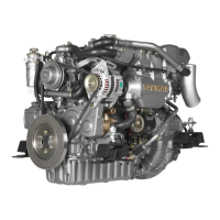
(a}
Assemble the shifting mechanism (without installing
the stopper bolt of the shifter) to the marine gear
case.
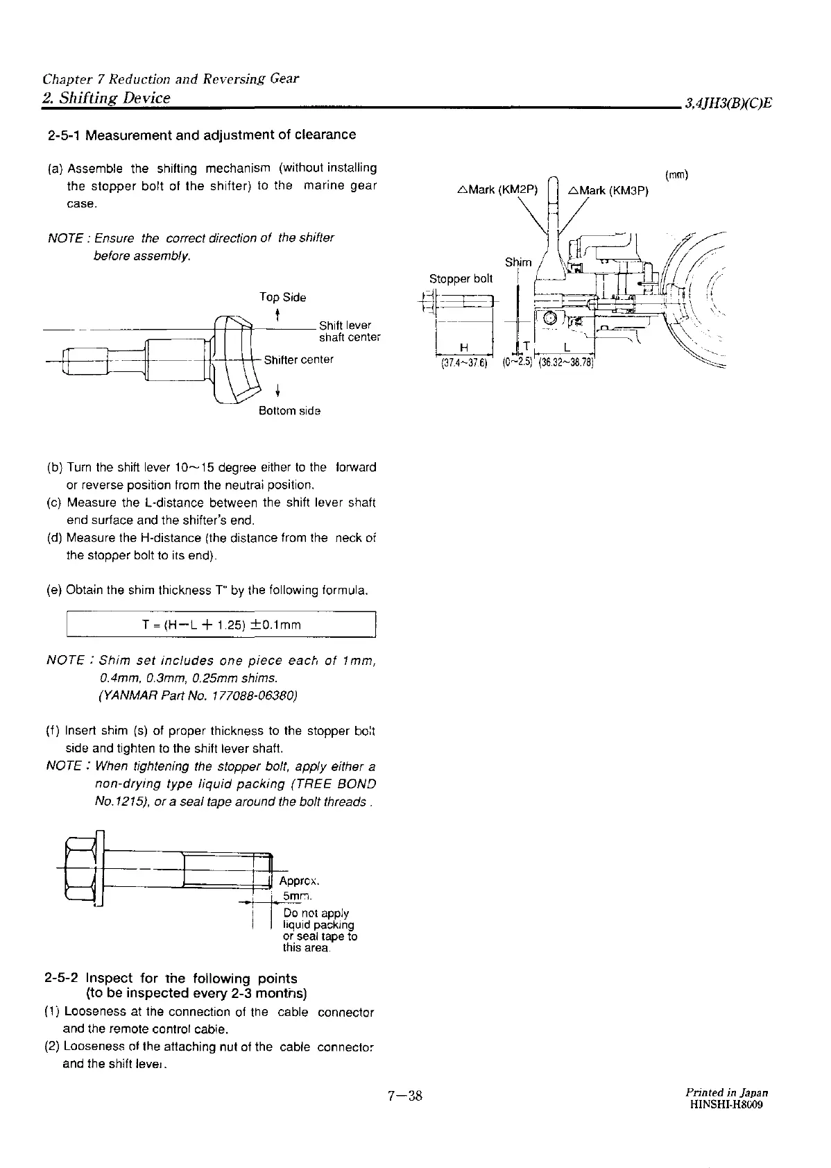
NOTE : Ensure the correct direction
of
the shifter
before assembly.
Top
Side
t
--
~
--------+-+----Pl-----
Shift
lever
shaft
center
Bottom
side
(b)
Turn
the
shift lever
10~15
degree either
to
the
forward
or reverse position from the neutrai position.
(c}
Measure the L-distance between the shift lever shaft
end surface and the shifter's end.
(d}
Measure the H-distance (the distance from the neck oi
the stopper bolt to its end).
(e)
Obtain the shim thickness
T"
by
the
following formula.
T =
(H-L
+ 1.25)
±0.1mm
NOTE
:
Shim
set
includes
one
piece
each
of
1 mm,
0.4mm, 0.3mm, 0.25mm shims.
(YANMAR
Part
No.
177088-06380)
(f) Insert shim
(s)
of proper thickness to the stopper
bo:t
side and tighten
to
the shift lever shaft.
NOTE :
When
tightening the stopper bolt, apply either a
non-drying
type
liquid
packing
(TREE
BOND
No.1215),
or
a seal tape around
the
bolt threads.
Rll--------1:.]
====i::::=lili
! App,o,.
BJ
mmr.i.
not
apply
q id packing
or seal tape to
this
area.
2-5-2 Inspect
for
the following points
(to
be
inspected every 2-3 months)
(1) Looseness at the connection of the cable connector
and the remote control cabie.
(2)
Looseness ot the attaching nut of the cable connector
and the shift
leve1.
7-38
Printed in Japan
HINSHI-H8009