Chapter 3 Fuel Injection
Equipment
.:::3:..
•
.::D.:;is:.:a:.:;s.:;.se:;:m=b:::lY..:•..:R.::.;e:.:a:.::s.:;.se:.:m=b:::lJ;..'
;;;.an;..d;.;....In..;.s;.:p;..;e;.;;c;;.t1;..·o_n_o_f_F_u;..e;..;l..;;I;..n..,ie'"'c..;.t1..;;·o_n...;P;..u;;.m...:.p
________
3
•
4
JHJ(B)(CJE
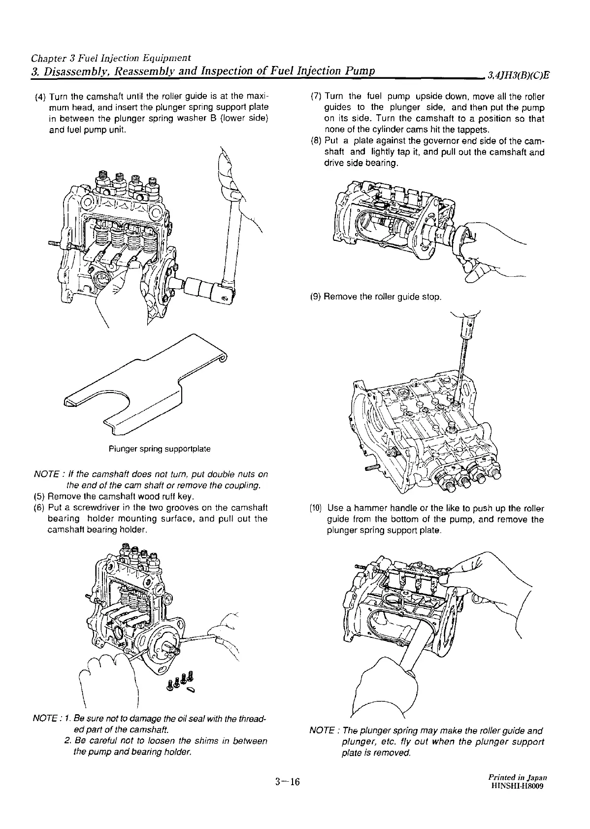
(4)
Turn the camshaft until the roller guide
is
at
the maxi-
mum head, and insert the plunger spring support plate
in
between the plunger spring washer B (lower side)
and fuel pump unit.
Piunger
spring
supportplate
NOTE : If the camshaft does not turn, put double nuts on
the end
of
the cam shaft
or
remove the coupling.
(5)
Remove the camshaft wood ruff key.
(6)
Put a screwdriver
in
the two grooves
on
the camshaft
bearing holder mounting surface, and pull out the
camshaft bearing holder.
NOTE :
1.
Be
sure not
to
damage the oil seal
with
the
thread-
ed
part
of
the camshaft.
2.
Be
careful not
to
loosen the shims
in
between
the pump and bearing holder.
3-16
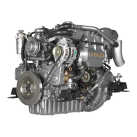
(7)
Turn the fuel pump upside down, move all the roller
guides to the plunger side, and then put the pump
on
its side. Turn the camshaft to a position
so
that
none
of
the cylinder cams hit the tappets.
(8)
Put a plate against the governor end side of the cam-
shaft and lightly tap
it,
and pull out the camshaft and
drive side bearing.
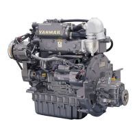
(9)
Remove the roller guide stop.
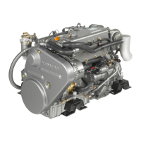
(10)
Use a hammer handle or the like to push up the roller
guide from the bottom of the pump, and remove the
plunger spring support plate.
NOTE :
The
plunger spring may make the roller guide
and
plunger, etc. fly
out
when the
plunger
support
plate is removed.
Printed
in
Japan
HINSHl-118009