Chapter 3 Fuel Injection Equipment
5. Injection Pump Construction and Operation
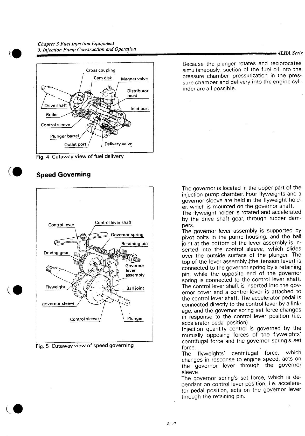
Cross
coupling
Cam
disk Magnet valve
Distributor
head
Inlet
port
Control sleeve
Plunger
barrel
Outlet
port
Delivery valve
fl
:
ig.
4 Cutaway view of fuel delivery
Speed
Governing
(
Control lever
Control lever shaft
1^ Governor spring
Flyweight
governor sleeve
Retaining pin
Governor
lever
^1 assembly
Control sleeve
Ball
joint
Plunger
Fig.
5 Cutaway view of speed governing
• 4LHA Serie
Because
the plunger rotates and reciprocates
simultaneously, suction of the fuel oil
into
the
pressure
chamber, pressurization in the pres-
sure chamber and delivery
into
the engine
cyl-
inder are all possible.
The governor is located in the upper
part
of the
injection pump chamber. Four flyweights and a
governor sleeve are held in the
flyweight
hold-
er, which is mounted on the governor shaft.
The
flyweight
holder is rotated and accelerated
by the drive shaft gear, through rubber dam-
pers.
The governor lever assembly is supported by
pivot
bolts in the pump housing, and the ball
joint
at the
bottom
of the lever assembly is in-
serted
into
the control
sleeve,
which slides
over the outside surface of the plunger. The
top of the lever assembly {the tension lever) is
connected to the governor spring by a retaining
pin,
while the opposite end of the governor
spring is connected to the control lever shaft.
The control lever shaft is inserted
into
the gov-
ernor cover and a control lever is attached to
the control lever shaft. The accelerator pedal is
connected directly to the control lever by a link-
age,
and the governor spring set force changes
in response to the control lever position (i.e.
accelerator pedal position).
Injection
quantity
control is governed by the
mutually opposing forces of the flyweights'
centrifugal force and the governor spring's set
force.
The flyweights' centrifugal force, which
changes
in response to engine
speed,
acts on
the governor lever through the governor
sleeve.
The governor spring's set force, which is de-
pendant on control lever position, i.e.
accelera-
tor pedal position, acts on the governor lever
through the retaining pin.
3-1-7

 Loading...


