Chapter 3 Fuel Injection Equipment
9. Pump Reassembly, Adjustment and Inspection
i
4LHA
Series
i
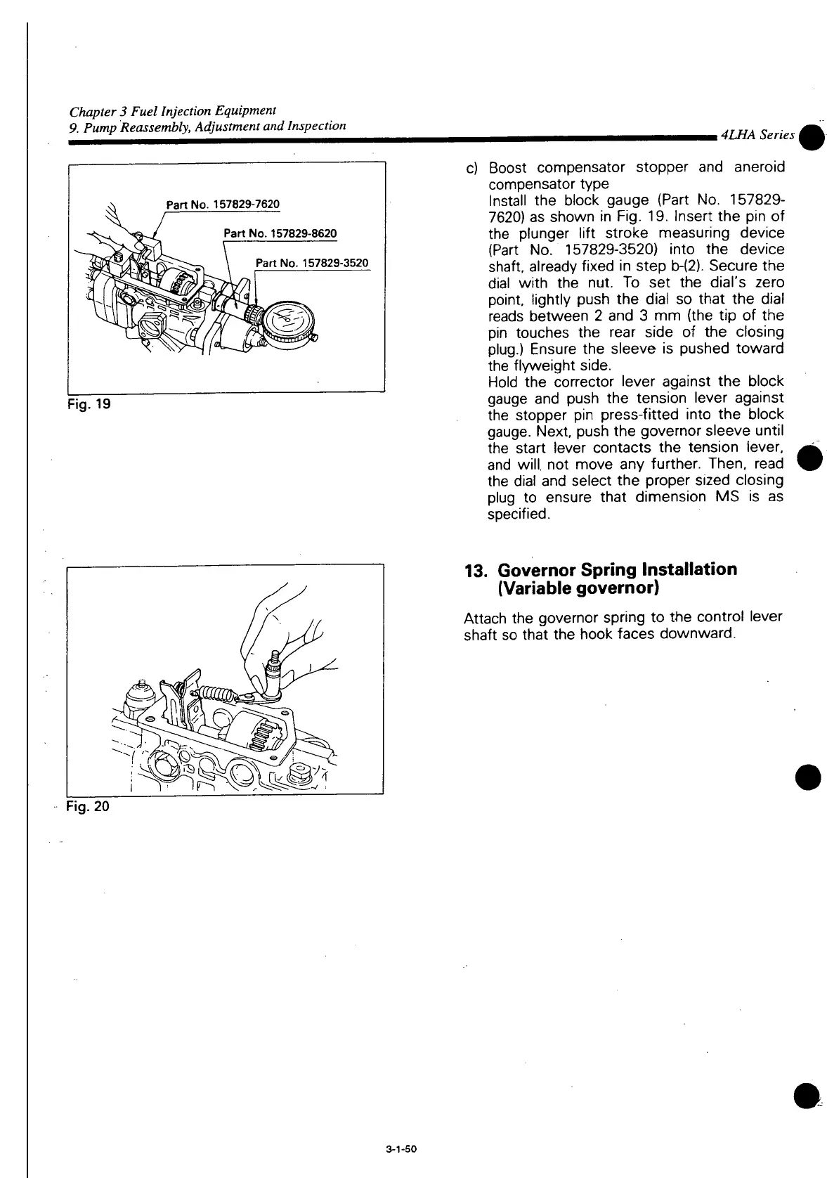
Part
No. 157829-7620
Part
No. 157829-8620
Part
No. 157829-3520
Fig.
19
c) Boost compensator stopper and aneroid
compensator type
Install
the block gauge (Part No. 157829-
7620) as shown in Fig. 19.
Insert
the pin of
the plunger
lift
stroke measuring device
(Part No. 157829-3520)
into
the device
shaft, already fixed in step
b-(2).
Secure the
dial
with
the nut. To set the dial's zero
point,
lightly
push the dial so
that
the dial
reads
between 2 and 3 mm (the tip of the
pin touches the rear side of the closing
plug.) Ensure the sleeve is pushed toward
the
flyweight
side.
Hold the corrector lever against the block
gauge and push the tension lever against
the stopper pin press-fitted
into
the block
gauge.
Next, push the governor sleeve
until
the
start
lever contacts the tension lever,
and will, not move any
further.
Then, read
the dial and select the proper
sized
closing
plug to ensure
that
dimension MS is as
specified.
13.
Governor Spring
Installation
(Variable
governor)
Attach the governor spring to the control lever
shaft so
that
the hook faces downward.
Fig.
20
3-1-50

 Loading...


