Chapter
3
Fuel Injection Equipment
9. Pump Reassembly, Adjustment and Inspection
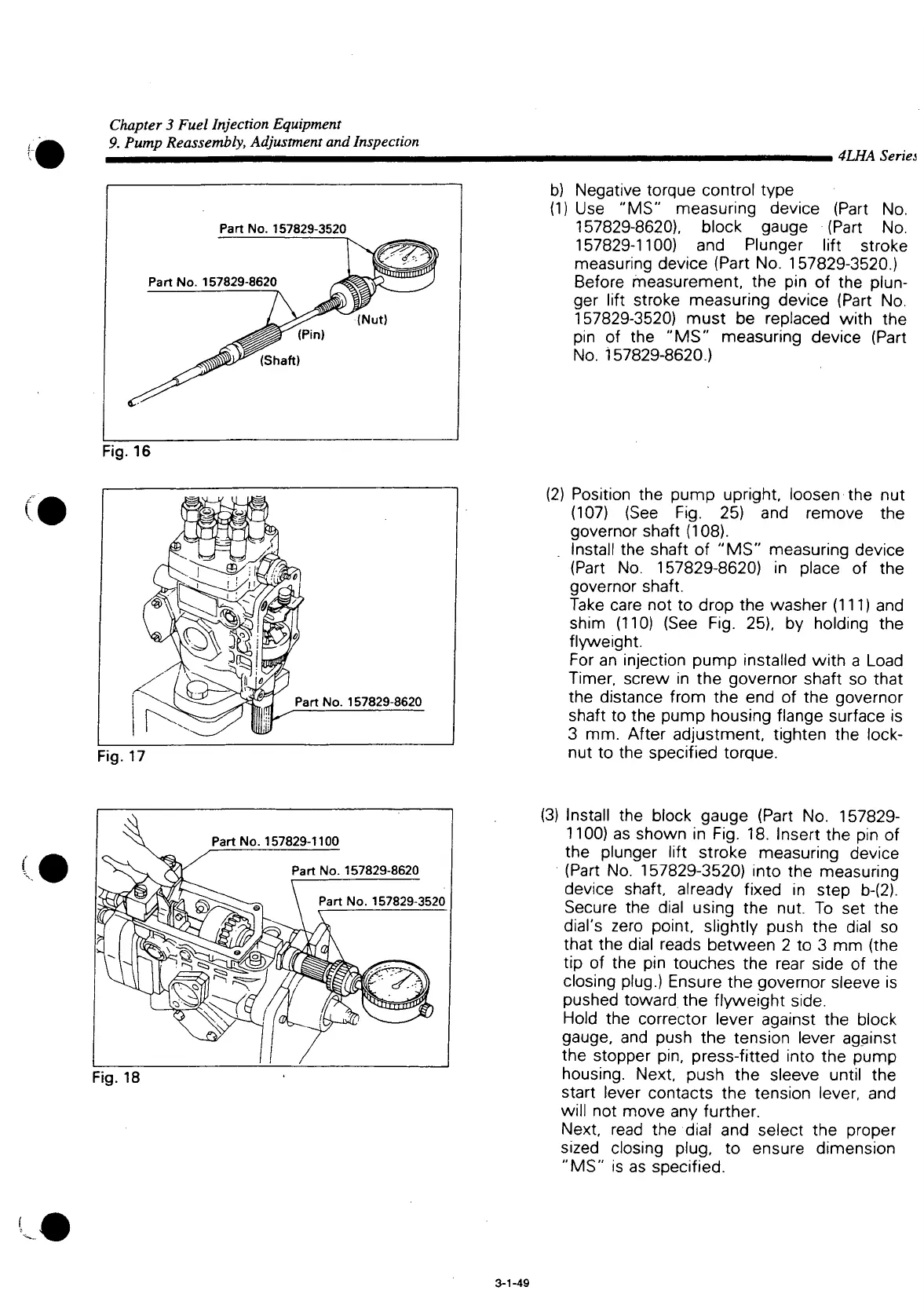
Part
No. 157829-3520
Part
No. 157829-8620
(Shaft)
Fig.
16
i
4LHA Series
b) Negative torque control type
(1)
Use "MS"
measuring device (Part
No.
157829-8620). block gauge (Part
No.
157829-1100)
and
Plunger
lift
stroke
measuring device (Part No. 157829-3520.)
Before measurement,
the pin of the
plun-
ger
lift
stroke measuring device (Part
No.
157829-3520) must
be
replaced
with
the
pin
of the "MS"
measuring device (Part
No.
157829-8620.)
Fig.
17
(2) Position
the
pump
upright,
loosen
the nut
(107)
(See Fig. 25) and
remove
the
governor shaft (108).
Install
the
shaft
of
"MS" measuring device
(Part
No.
157829-8620)
in
place
of the
governor shaft.
Take
care
not to
drop
the
washer
(111) and
shim
(110) (See Fig. 25), by
holding
the
flyweight.
For
an
injection pump installed
with
a
Load
Timer, screw
in the
governor shaft
so
that
the distance
from
the end of the
governor
shaft
to the
pump housing flange surface
is
3
mm.
After adjustment,
tighten
the
lock-
nut
to the
specified torque.
Part
No.
157829-1100
Part
No.
157829-8620
Part
No.
157829-3520
Fig.
18
(3)
Install
the
block gauge (Part
No.
157829-
1100)
as
shown
in
Fig.
18.
Insert
the pin of
the plunger
lift
stroke measuring device
(Part
No.
157829-3520)
into
the
measuring
device
shaft, already fixed
in
step
b-(2).
Secure
the
dial using
the nut. To set the
dial's
zero point, slightly push
the
dial
so
that
the
dial reads between
2 to 3 mm (the
tip
of the pin
touches
the
rear side
of the
closing
plug.) Ensure
the
governor sleeve
is
pushed toward,
the
flyweight
side.
Hold
the
corrector lever against
the
block
gauge,
and
push
the
tension lever against
the stopper
pin,
press-fitted
into
the
pump
housing.
Next, push
the
sleeve
until
the
start
lever contacts
the
tension lever,
and
will
not
move
any
further.
Next, read
the
dial
and
select
the
proper
sized
closing plug,
to
ensure dimension
"MS"
is as
specified.
3-1-49

 Loading...


