Chapter 3 Fuel Injection Equipment
9. Pump Reassembly, Adjustment and Inspection
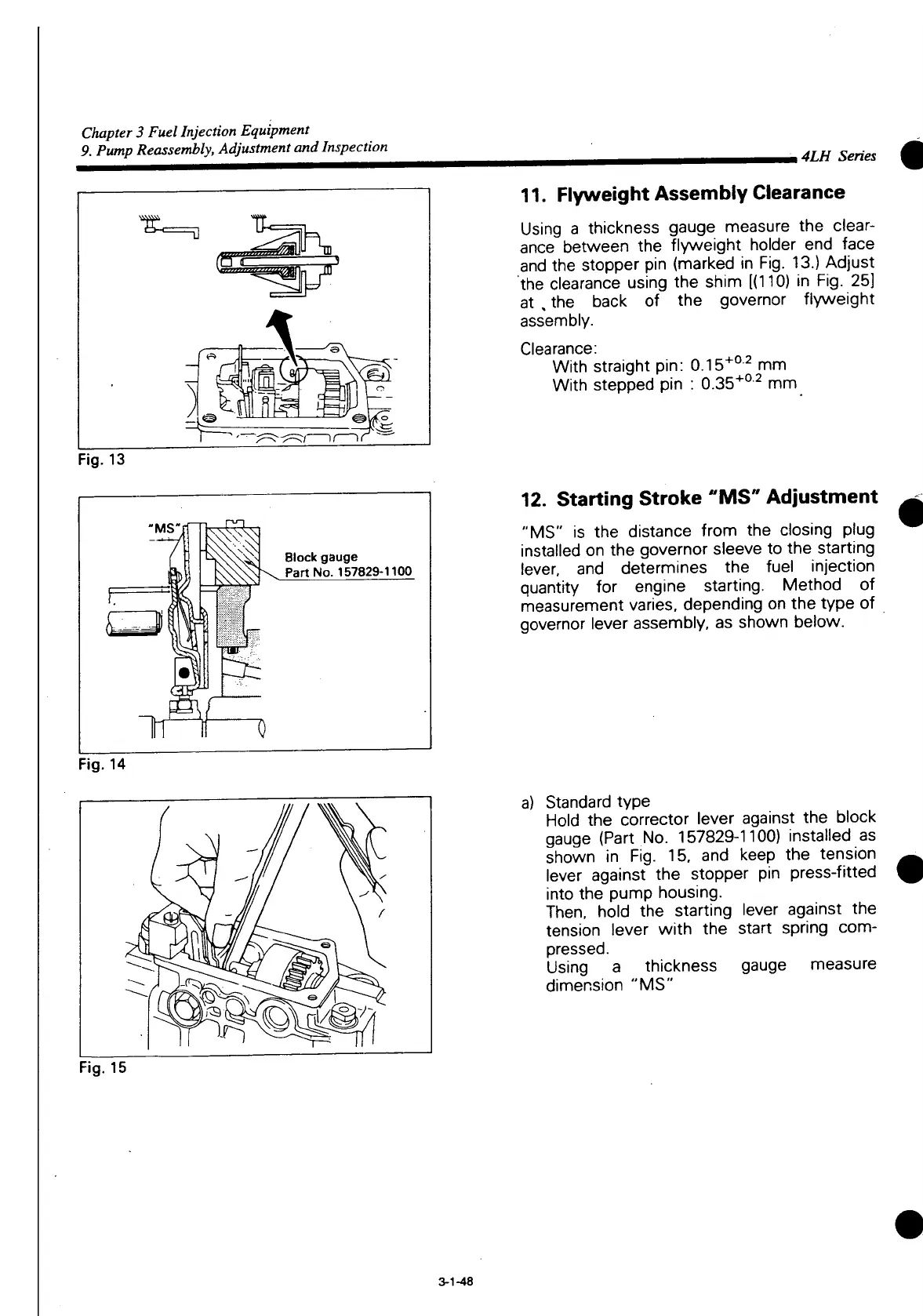
Fig.
13
Block
gauge
Part
No. 157829-1100
n 0
Fig.
14
_ 4LH Series
11.
Flyweight
Assembly
Clearance
Using
a thickness gauge measure the clear-
ance
between the
flyweight
holder end face
and the stopper pin (marked in Fig. 13.) Adjust
the clearance using the shim
[(110)
in Fig. 25]
at , the back of the governor
flyweight
assembly.
Clearance:
With straight pin: 0.15
+0 2
mm
With stepped pin : 0.35
+0 2
mm
12.
Starting
Stroke
"MS"
Adjustment
"MS"
is the distance
from
the closing plug
installed on the governor sleeve to the starting
lever, and determines the fuel injection
quantity
for engine starting. Method of
measurement varies, depending on the type of
governor lever assembly, as shown below.
a) Standard type
Hold the corrector lever against the block
gauge (Part No. 157829-1100) installed as
shown in Fig. 15, and keep the tension
lever against the stopper pin press-fitted
into
the pump housing.
Then,
hold the starting lever against the
tension lever
with
the
start
spring
com-
pressed.
Using
a thickness gauge measure
dimension "MS"
Fig.
15
3-1-48

 Loading...


