Chapter 3 Fuel Injection Equipment
5. Injection Pump Construction and Operation
Injection
Timing
Control
Roller
holder
Roller
holder pin
High
pressure
side
Timer piston
Timer spring
i 4LHA Series
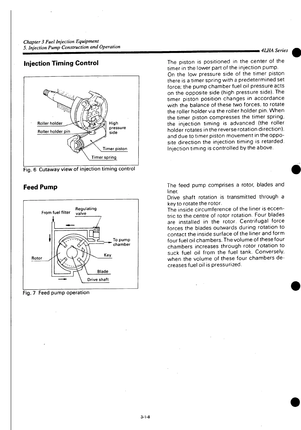
The
piston is positioned in the center of the
timer in the lower part of the injection pump.
On
the low pressure side of the timer piston
there is a timer spring
with
a predetermined set
force;
the pump chamber fuel oil pressure acts
on the opposite side (high pressure side). The
timer piston position changes in accordance
with
the balance of these two forces, to rotate
the roller holder via the roller holder pin. When
the timer piston compresses the timer spring,
the injection timing is advanced (the roller
holder rotates in the reverse rotation direction),
and
due to timer piston movement in the oppo-
site direction the injection timing is retarded.
Injection timing is controlled by the above.
:
ig.
6 Cutaway view of injection timing control
Feed Pump
Regulating
From
fuel
filter
va
|ve
Rotor
To
pump
" chamber
Key
Blade
Drive shaft
Fig.
7
Feed
pump operation
The
feed pump comprises a rotor, blades and
liner.
Drive shaft rotation is transmitted through a
key
to rotate the rotor.
The
inside circumference of the liner is
eccen-
tric to the centre of rotor rotation. Four blades
are installed in the rotor. Centrifugal force
forces
the blades outwards during rotation to
contact the inside surface of the liner and form
four fuel oil chambers. The volume of these four
chambers
increases through rotor rotation to
suck
fuel oil from the fuel tank. Conversely,
when the volume of these four chambers de-
creases
fuel oil is pressurized.
3-1-a
 Loading...


