Programming 110
For example, if H4-02= 150%, then the FM analog output will produce 6.7Vdc when the assigned output function initially
reached the 100% level.
Fig. 78 Analog Output gain Setting Adjustment
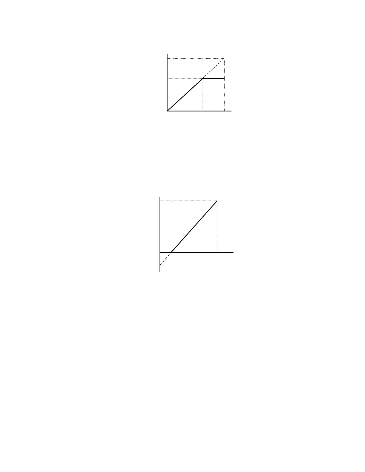
Like the bias settings for the analog inputs (H3-03 and H3-11), the bias settings for the analog outputs determine the output
function level that will be equivalent to 0Vdc or 4mA.
For example, if H4-03= -25%, then when the output function level is at 0% the FM analog output will output 2Vdc.
Fig. 79 Analog Output Bias
H4-04 Terminal AM Monitor Selection
Setting Range: 1 to 45
Factory Default: 3: Output Current
Refer to parameter H4-01 for description details.
H4-05 Terminal AM Gain Setting
Setting Range: 0.0 to 1000.0%
Factory Default: 50.0%
H4-06 Terminal AM Bias Setting
Setting Range: -110.0% to +110.0%
Factory Default: 0.0%
Refer to parameters H4-02 & H4-03 for description details.
100%
10V
0
Output
Function
Level
Analo
Out
ut
150%
~6.7V
Monitor
Function
Level
Analog Output Level
10V x 150%
10V
67%
100%
100%
10V
0
Output
Function
Level
Analog Output
2V
-25%
 Loading...


