Programming 18
b4 Delay Timers
The Drive has an internal timer function that operates independently from the Drive. A digital input must be programmed to be
a timer start input by setting H1-0x= 18. A digital output must be programmed as a timer output by setting H2-0x= 12. (Not to
be confused with the “Wait to Run Time” in b1-11)
b4-01 Timer Function ON-Delay Time
Setting Range: 0.0 to 3000.0 Seconds
Factory Default: 0.0 Seconds
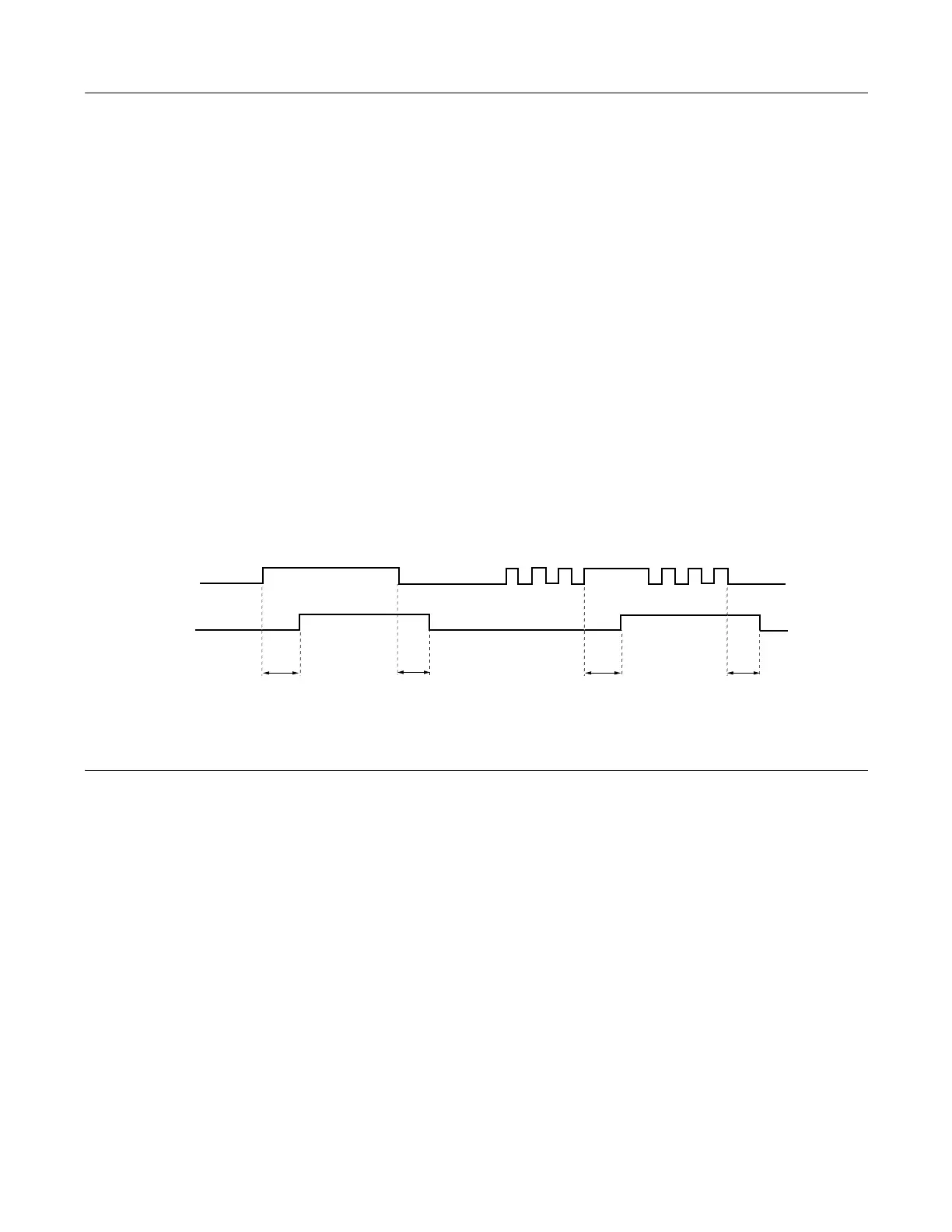
The timer start input (H1-0x= 18) must be held on for at least the time specified in parameter b4-01 before the digital output
programmed as the timer output will close. See Figure below for timing details.
b4-02 Timer Function OFF-Delay Time
Setting Range: 0.0 to 3000.0 Seconds
Factory Default: 0.0 Seconds
The timer start input (H1-0x= 18) must be held off for at least the time specified by b4-02 before the digital output
programmed as the timer output will open. See Figure below for timing details.
Fig. 15 Timing Diagram of Timer Function
b5 PID Function
The capability to accept an analog signal as feedback for a PID (Proportional + Integral + Derivative) control function is built
into the Drive. The PID control function provides closed-loop control and regulation of a system variable such as temperature
or pressure. A control signal based on the difference (or proportion) between a feedback signal and a desired setpoint is
produced. Integration and derivative calculations are then performed on this signal, based upon the PID parameter settings
(B5-01 to B5-19), to minimize deviation, for more precise control.
Proportional - P
PID refers to the type of action used to control modulating equipment such as valves or dampers. With proportional control, a
control signal based on the difference between an actual condition and a desired condition is produced. The difference, such as
that between an actual temperature and setpoint is the “error”. The inverter adjusts its output signal related directly to the error
magnitude.
Integral - I
The integral action is designed to minimize offset. An integrating term is used to observe how long the error condition has
existed, summing the error over time. Once the system has stabilized, the offset would be minimized.
Multi-function Contact
Input: Timer Function
Multi-function Contact
Output: Timer Function
B4-01
B4-01
B4-02
ON (CLOSED)
OFF (OPEN)
ON (CLOSED
OFF (OPEN)
B4-02
 Loading...


