NOTICE: Do not connect phase-advancing capacitors or LC/RC noise filters to the output circuits. Improper
application of noise filters could result in damage to the drive.
CB
A
D
R/L1
MCCB
S/L2
T/L3
U/T1
V/T2
W/T3
1
2
3
4
5
6
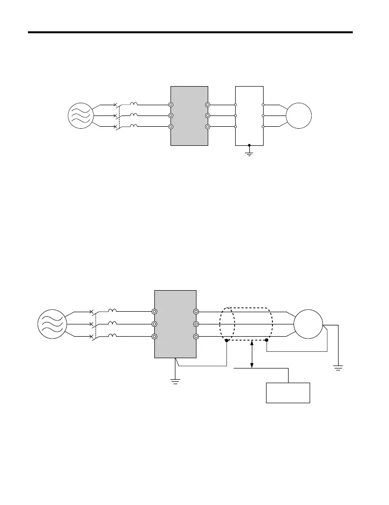
A – Power supply
B – Drive
C – Output-side noise filter
D – Motor
Figure 7.7 Output-Side Noise Filter
• Radiated Noise: Electromagnetic waves radiated from the drive and cables create noise
throughout the radio bandwidth that can affect devices.
• Induced Noise: Noise generated by electromagnetic induction can affect the signal line
and may cause the controller to malfunction.
Preventing Induced Noise
Use a noise filter on the output
side or use shielded cables. Lay the cables at least 30 cm away
from the signal line to prevent induced noise.
B
A
C
F
G
D
E
R/L1
MCCB
S/L2
T/L3
U/T1
V/T2
W/T3
A – Power supply
B – Drive
C – Shielded motor cable
D – Motor
E – Separate at least 30 cm
F – Controller
G – Signal line
Figure 7.8 Preventing Induced Noise
7.4 Installing Peripheral Devices
196
YASKAWA ELECTRIC TOEP C710606 25D YASKAWA AC Drive J1000 Installation & Start-Up Manual
 Loading...


