6 Parameter Table
YASKAWA ELECTRIC
TOEP C710606 15E - AC Drive V1000 - Quick Start Guide
EN 29
Par. Name Description
C1-03
to
C1-08
Accel/Decel
Times 2 to 4
Set the accel/decel times 2 to 4 (set
like C1-01/02).
C2-01 S-Curve 1 S-curve at acceleration start.
C2-02 S-Curve 2 S-curve at acceleration end.
C2-03 S-Curve 3 S-curve at deceleration start.
C2-04 S-Curve 4 S-curve at deceleration end.
Slip Compensation
C3-01
Slip
Compensa-
tion Gain
• Increase if the speed is lower
than the frequency reference.
• Decrease if the speed is higher
than the frequency reference.
C3-02
Slip
Compensa-
tion Delay
Time
• Decrease the setting when the
slip compensation is too slow.
• Increase the setting when the
speed is not stable.
Torque Compensation
C4-01
Torque
Compensa-
tion Gain
• Increase this setting when the
torque response is slow.
• Decrease this setting when
speed/torque oscillations occur.
C4-02
Torque
Compensa-
tion Delay
Time
• Increase this setting when speed
/torque oscillations occur.
• Decrease the setting when the
torque response is too slow.
Duty Mode and Carrier Frequency
C6-01
Normal/
Heavy Duty
Selection
0: Heavy Duty (HD)
Constant torque applications
1:Normal Duty (ND)
Variable torque application
C6-02
Carrier
Frequency
Selection
1:2.0 kHz
2:5.0 kHz
3:8.0 kHz
4:10.0 kHz
5:12.5 kHz
6:15.0 kHz
7 to A: Swing PWM1 to 4
B: Leakage Current Rejection
PWM
F: User defined
Frequency References
d1-01
to
d1-16
Frequency
Reference
1 to 16
Set the multi-speed references 1 to
16.
d1-17 Jog Speed Jog speed
V/f Pattern
E1-01
Input
Voltage
Setting
Input Voltage
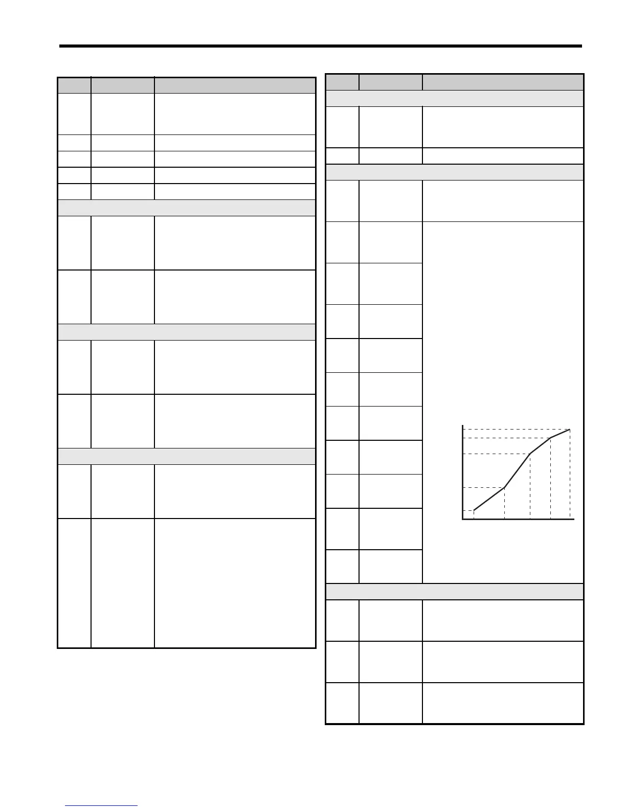
E1-04
Max.
Output
Frequency
For a linear V/f characteristics, set
the same values for E1-07 and
E1-09. In this case, the setting for
E1-08 will be disregarded.
Ensure that the five frequencies
are set according to these rules or
an oPE10 fault will occur:
E1-09 E1-07 E1-06-
E1-04
Note: Setting E1-11 to 0 disables
both E1-11 and E1-12, and the
above conditions do not apply.
E1-05
Max.
Output
Voltage
E1-06
Base
Frequency
E1-07
Mid. Output
Frequency
E1-08
Mid. Output
Vo l t a g e
E1-09
Min. Output
Frequency
E1-10
Min. Output
Vo l t a g e
E1-11
Mid. Output
Frequency 2
E1-12
Mid. Output
Frequency
Voltage 2
E1-13
Base
Vo l t a g e
Motor Data
E2-01
Motor
Rated
Current
Automatically set during
Auto-Tuning.
E2-02
Motor
Rated Slip
Motor rated slip in hertz (Hz).
Automatically set by Rotational
Auto-Tuning.
E2-03
Motor
No-Load
Current
Magnetizing current in Ampere.
Automatically set by Rotational
Auto-Tuning.
Par. Name Description
Output Voltage (V)
Frequency (Hz)
E1-05
E1-12
E1-13
E1-08
E1-10
E1-09 E1-07 E1-06 E1-11 E1-04
 Loading...


