2.4 EMC Installation Conditions
2-11
2.4 EMC Installation Conditions
This section describes the recommended installation conditions that satisfy EMC
guidelines when combining a SGDV SERVOPACK in the DC power input Σ-V series
with a SGM7M servomotor in the Σ-7mini series or a SGMMV servomotor in the Σ-
Vmini series.
The recommended installation conditions for SERVOPACKs with
MECHATROLINK-III communications are described here. For SERVOPACKs with
a different interface, refer to the following installation conditions.
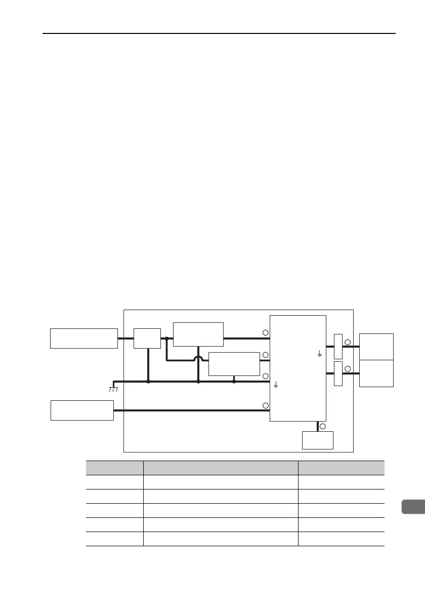
The following illustration shows the EMC installation conditions satisfied in test con-
ditions prepared by Yaskawa. The actual EMC level may differ depending on the
actual system’s configuration, wiring, and other conditions. However, because this
product is built-in, check that the following conditions are still met after being
installed in the user’s product.
The applicable standards are EN55011 group 1 class A, EN 61000-6-2, EN 61000-6-
4, and EN 61800-3 (Category C2, Second environment).
2.4.1 SGDV-E21A (M-III Model)
SGDV-E21A ( = 1R7, 2R9)
Symbol Cable Name Specification
I/O signal cable Shield cable
Servomotor main circuit cable Shield cable
Encoder cable Shield cable
Power supply cable Without shield cable
MECHATROLINK-III communication cable Shield cable
L1, L2
C1, C2
CN3
CN3
CN3
CN6A, CN6B
CN1
CN2
CN4
2
1
3
4
4
4
5
FG
U,V,W
Main circuit
power supply
AC/DC: 48 VDC
Control power
supply
AC/DC: 24 VDC
Power supply:
Single-phase 200 VAC
MECHATROLINK-III
controller
Noise
filter
Host
controller
Shield box
SERVOPACK
Encoder
Servomotor
ClampClamp
 Loading...


