20 Troubleshooting
YASKAWA TOEPC7106171FD FP605 DRIVE INSTALLATION & PRIMARY OPERATION 121
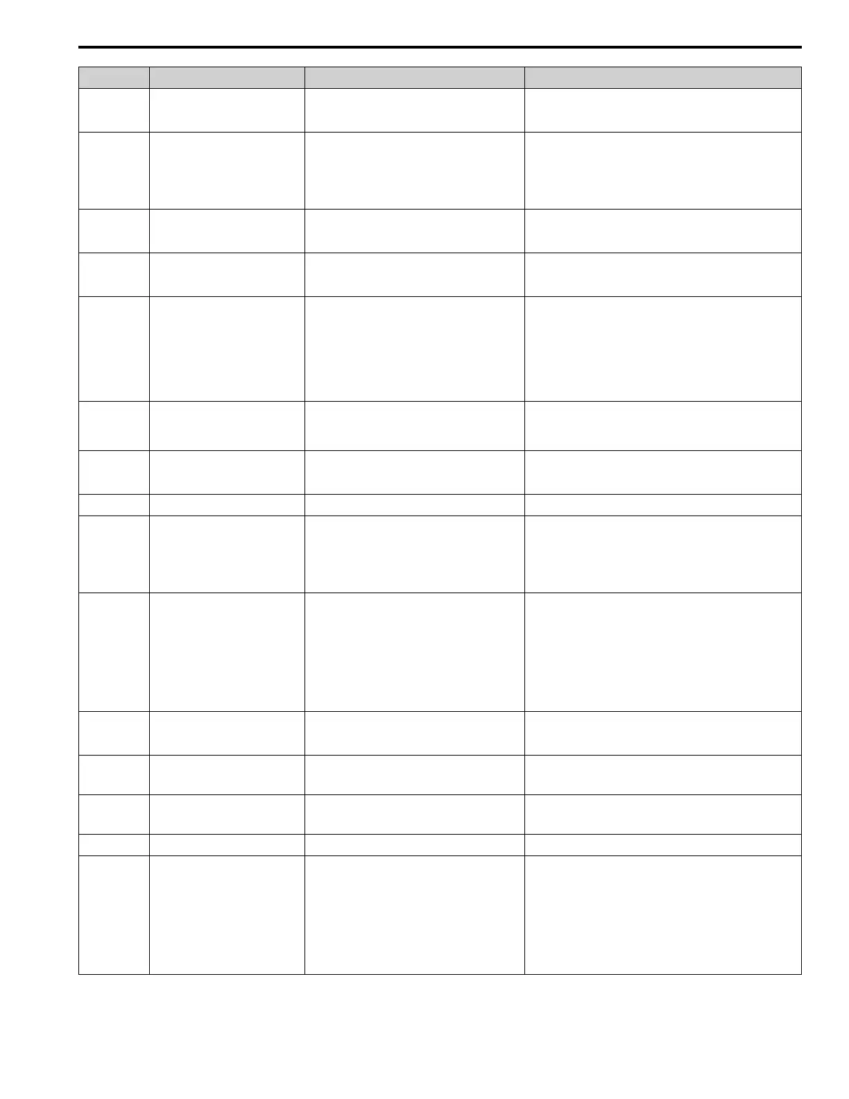
Code Name Causes Possible Solutions
HCA High Current Alarm
The load is too heavy. • Decrease the load for applications with repetitive starts and
stops.
• Replace the drive with a larger capacity model.
HIAUX High PI Aux Feedback Level
PI Auxiliary Feedback is more than the level set in
YF-12 [PI Aux Control High Level Detect] for the
time set in YF-13 [PI Aux High Level Detection Time]
in these conditions:
• The drive is running.
• The output frequency > 0.
• Decrease the PI Auxiliary Feedback level to less than YF-12.
• Set YF-12 and YF-13 correctly.
HIFB High Feedback Sensed
The feedback level is more than the level set in Y1-11
[High Feedback Level].
• Decrease the feedback level to less than Y1-11 - Y1-14
[Hysteresis Level].
• Set Y1-11 and Y1-12 correctly.
L24v Loss of External Power 24 Supply
The voltage of the backup 24 V power supply has
decreased. The main circuit power supply is operating
correctly.
• Examine the external 24 V power supply for disconnected wires
and wiring errors and repair the problems.
• Examine the external 24 V power supply for problems.
LCP Low City Pressure
Insufficient pressure is present on the inlet to the
pump in these conditions:
• Y4-24 = 0 [Low City Alarm Text = Low City
Pressure]
• The terminal set for H1-xx = B8 or 1B8 [MFDI
Function Selection = Low City Pressure or !Low
City Pressure] activates
• Examine the pressure switch contact for correct operation.
• Examine control wiring to drive terminal strip from pressure
switch contact.
• Make sure that suction pressure is present with an isolated
measuring device.
• Set Y4-22 [Low City On-Delay Time] and Y4-23 [Low City Off-
Delay Time] correctly.
• Deactivate the digital input terminals set to H1-xx = B8 or 1B8.
LOAUX Low PI Aux Feedback Level
When the drive is running, PI Auxiliary Feedback is
less than the level set in YF-09 [PI Aux Control Low
Lvl Detection] for the time set in YF-10 [PI Aux
Control Low Lvl Det Time].
• Increase the PI Auxiliary Feedback level more than YF-09.
• Set YF-09 and YF-10 correctly.
LOFB Low Feedback Sensed
The feedback level is less than the level set in Y1-08
[Low Feedback Level] for the time set in Y1-09 [Low
Feedback Lvl Fault Dly Time].
• Increase the feedback level to more than Y1-08 + Y1-14 [High
Feedback Hysteresis Level].
• Set Y1-08 and Y1-09 correctly.
LoG Com Error / Abnormal SD Card
There is not a micro SD card in the keypad. Put a micro SD card in the keypad.
LOP Loss of Prime
The drive used the method set in Y1-18 [Prime Loss
Detection Method] to detect that the pump load is less
than the level set in Y1-19 [Prime Loss Level] for the
time set in Y1-20 [Prime Loss Time], and the output
frequency is Y1-21 [Prime Loss Activation Freq] or
more.
• Examine a dry well, air in the system, or no water in the system.
Use preferred priming method suggested by the pump
manufacturer to restart the pump.
• When there is resistance in the pump, allow the system to pump
water again.
• Set Y1-18 to Y1-21 correctly.
LSP Low Suction Pressure
An external input has indicated that an insufficient
suction pressure condition exists in these conditions:
• Y4-24 = 1 [Low City Alarm Text = Low Suction
Pressure]
• The terminal set for H1-xx = B8 or 1B8 [MFDI
Function Selection = Low City Pressure or !Low
City Pressure] activates
• Examine the pressure switch contact for correct operation.
• Examine control wiring to drive terminal strip from pressure
switch contact.
• Make sure that suction pressure is present with an isolated
measuring device.
• Increase the system pressure.
• Set Y4-22 [Low City On-Delay Time] and Y4-23 [Low City Off-
Delay Time] correctly.
• Deactivate the digital input terminals set to H1-xx = B8 or 1B8.
LT-1 Cooling Fan Maintenance Time
The cooling fan is at 90% of its performance life
estimate.
1. Replace the cooling fan.
2. Set o4-03 = 0 [Fan Operation Time Setting = 0 h] to reset the
cooling fan operation time.
LT-2 Capacitor Maintenance Time
The capacitors for the main circuit and control circuit
are at 90% of their performance life estimate.
Replace the control board or the drive. For information about
replacing the control board, contact Yaskawa or your nearest sales
representative.
LT-3 SoftChargeBypassRelay MainteTime
The soft charge bypass relay is at 90% of its
performance life estimate.
Replace the control board or the drive. For information about
replacing the control board, contact Yaskawa or your nearest sales
representative.
LT-4 IGBT Maintenance Time (50%)
The IGBT is at 50% of its performance life estimate. Check the load, carrier frequency, and output frequency.
LWT Low Water In Tank
An external input has indicated that the water level in
the tank is too low in these conditions:
• Y4-24 = 2 [Low City Alarm Text = Low Water in
Tank]
• The terminal set for H1-xx = B8 or 1B8 [MFDI
Function Selection = Low City Pressure or !Low
City Pressure] activates
• Examine the pressure switch contact for correct operation.
• Examine control wiring to drive terminal strip from pressure
switch contact.
• Make sure that suction pressure is present with an isolated
measuring device.
• Increase the water level.
• Set Y4-22 [Low City On-Delay Time] and Y4-23 [Low City Off-
Delay Time] correctly.
• Deactivate the digital input terminals set to H1-xx = B8 or 1B8.