10 Drive Start-Up Procedure
62 YASKAWA TOEPC7106171FD FP605 DRIVE INSTALLATION & PRIMARY OPERATION
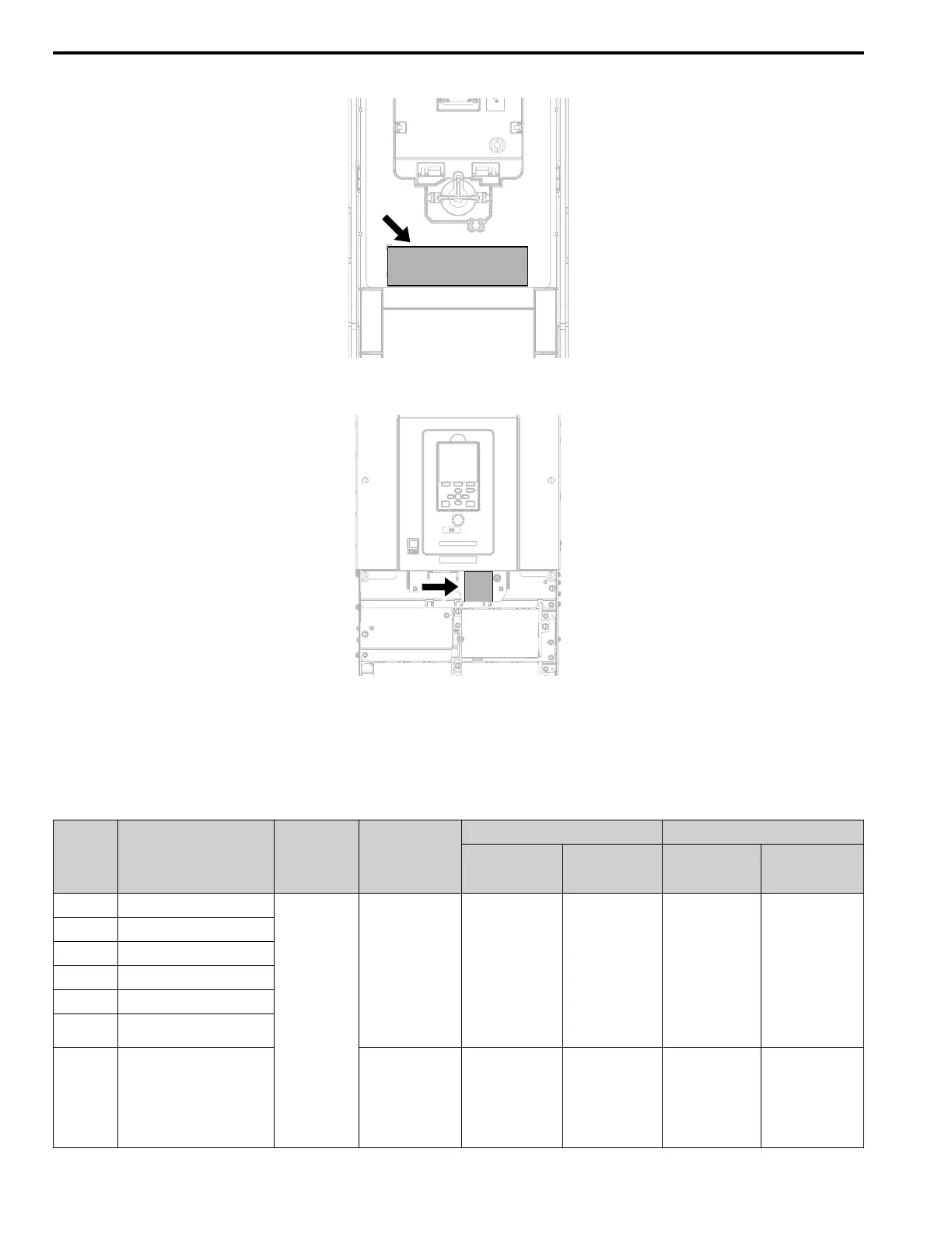
The tightening torque for the terminal screws is shown on the reverse side or the lower front side of the front cover.
Figure 10.2 Tightening Torque Display Location (Reverse Side of Front Cover)
Figure 10.3 Tightening Torque Display Location (Lower Front Side of Front Cover)
■ Control Circuit Wire Gauges and Tightening Torques
Use the tables in this section to select the correct wires. Use shielded wire to wire the control circuit terminal block.
Use crimp ferrules on the wire ends to make the wiring procedure easier and more reliable.
Table 10.6 Control Circuit Wire Gauges and Tightening Torques
Terminal
Block
Terminal Screw Size
Tightening Torque
N∙m (lbf∙in)
Bare Wire Crimp Ferrule
Recommended
Gauge
mm
2
(AWG)
Applicable Gauge
mm
2
(AWG)
Recommended
Gauge
mm
2
(AWG)
Applicable Gauge
mm
2
(AWG)
TB1 +V, AC, A1, A2, A3
M3
0.5 - 0.6
(4.4 - 5.3)
0.75
(18)
Stranded wire:
0.25 - 1.5
(24 - 16)
Solid wire:
0.25 - 1.5
(24 - 16)
0.75
(18)
0.25 - 1.5
(24 - 16)
TB3 FM, AM, AC, S1 - S8
TB4 SN, SC, SP, +P
TB5 SN, HC, H1, H2
TB6 AC, D+, D-, PS, RP
TB7
MA, MB, MC, MD, ME, MF, M1
- M4
TB2 FE
1.0 - 1.2
(8.85 - 10.62)
0.75
(18)
Stranded wire:
0.12 - 0.75
(26 - 18)
Solid wire:
0.2 - 1.5
(26 - 16)
0.75
(18)
0.25 - 1.5
(24 - 16)

 Loading...


