10 Drive Start-Up Procedure
66 YASKAWA TOEPC7106171FD FP605 DRIVE INSTALLATION & PRIMARY OPERATION
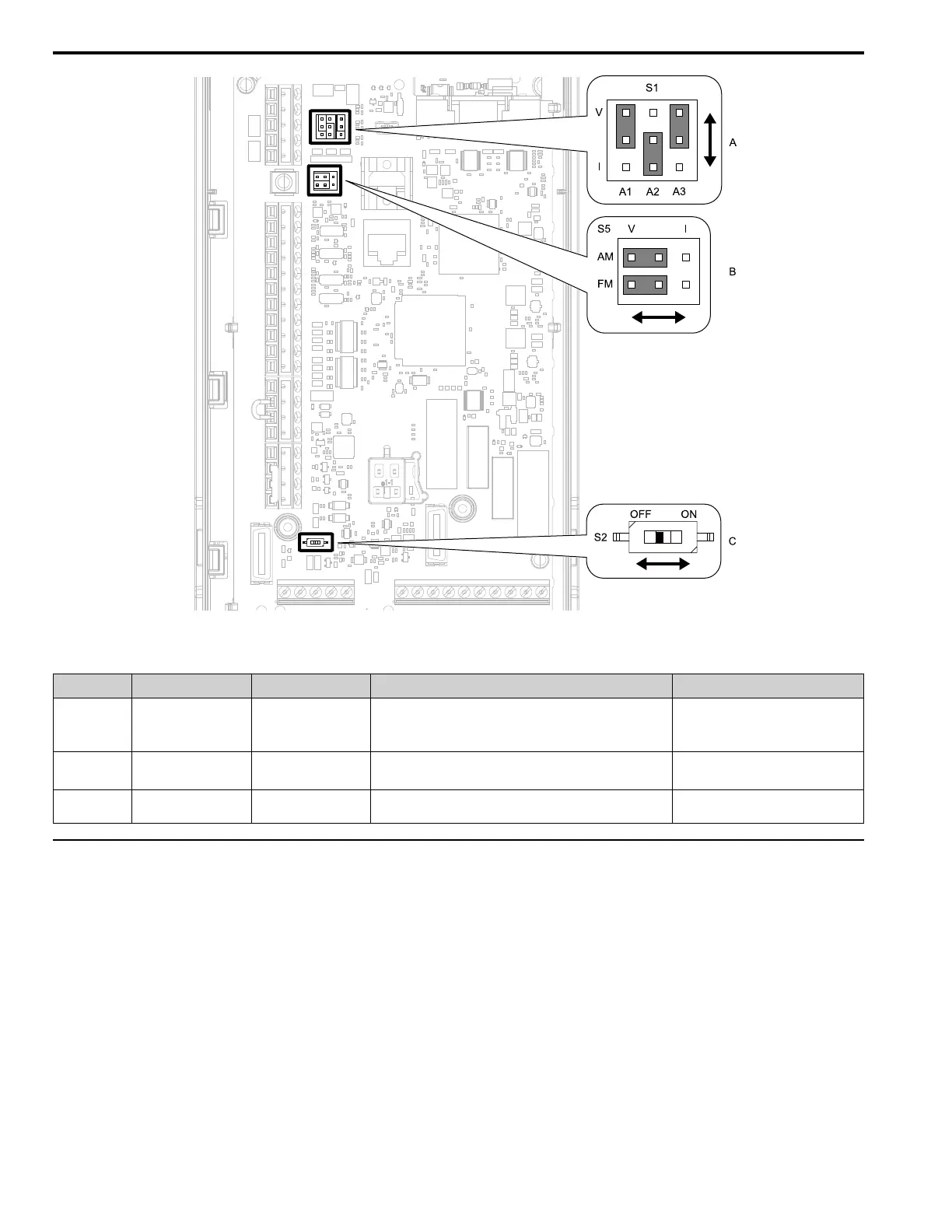
Figure 10.8 Locations of Switches
Table 10.8 I/O Terminals and Switches Functions
Position Switch Terminal Function Default Setting
A Jumper switch S1 A1, A2, A3 Sets terminals A1 to A3 to voltage or current output.
A1: V (voltage input)
A2: I (current input)
A3: V (voltage input)
B Jumper switch S5 FM, AM Sets terminals FM and AM to voltage or current output.
FM: V (voltage output)
AM: V (voltage output)
C DIP switch S2 -
Enables and disables the termination resistor of MEMOBUS/
Modbus communications.
OFF
◆ Control I/O Connections
This section gives information about the settings for the listed control circuit I/O signals.
• MFDI (terminals S1 to S8)
• MFDO (terminals M1 to M4 and MD to MF)
• MFAI (terminals A1 to A3)
• MFAO (terminals FM, AM)
• MEMOBUS/Modbus communications (terminals D+, D-, AC)
■ Set Sinking Mode/Sourcing Mode
Close the circuit between terminals SC-SP and SC-SN to set the sinking mode/sourcing mode and the internal/
external power supply for the MFDI terminals. The default setting for the drive is internal power supply sinking
mode.