u
Main Circuit Wiring
WARNING!
Electrical Shock Hazard. Do not connect the AC power line to the drive output terminals U/T1, V/T2, and W/T3 . Failure to
comply could result in death or serious injury by fire as a result of drive damage from line voltage application to output terminals.
NOTICE
Refer to the P1000 Technical Manual SIEPYAIP1U01 on the CD-ROM packaged with the product for complete product
instructions necessary for proper installation, set-up, troubleshooting and maintenance. CD part number TOECC71061615.
NOTICE:
Route motor leads U/T1, V/T2, and W/T3 separate from all other leads to reduce possible interference related issues. Failure to
comply may result in abnormal operation of drive and nearby equipment.
NOTICE:
Do not use the negative DC bus terminal “–” as a ground terminal. This terminal is at high DC voltage potential. Improper wiring
connections could damage the drive.
NOTICE:
Do not solder the ends of wire connections to the drive. Soldered wiring connections can loosen over time. Improper wiring practices
could result in drive malfunction due to loose terminal connections.
NOTICE:
Do not switch the drive input to start or stop the motor. Frequently switching the drive on and off shortens the life of the DC bus
charge circuit and the DC bus capacitors, and can cause premature drive failures. For the full performance life, refrain from switching the
drive on and off more than once every 30 minutes.
NOTICE:
When connecting the motor to the drive output terminals U/T1, V/T2, and W/T3, the phase order for the drive and motor should
match. Failure to comply with proper wiring practices may cause the motor to run in reverse if the phase order is backward.
NOTICE:
Do not connect phase-advancing capacitors or LC/RC noise filters to the output circuits. Failure to comply could result in damage
to the drive, phase-advancing capacitors, LC/RC noise filters or ground fault circuit interrupters.
Note: Wire gauge recommendations based on drive continuous current ratings (ND) using 75 °C 600 Vac vinyl-sheathed wire assuming ambient
temperature within 40 °C and wiring distance less than 100 m.
Yaskawa recommends using closed-loop crimp terminals on all drive models. To maintain UL/cUL approval, UL Listed
closed-loop crimp terminals are specifically required when wiring the drive main circuit terminals on models 2A0110 to
2A0415, 4A0058 to 4A1200, and 5A0041 to 5A0242. Use only the tools recommended by the terminal manufacturer for
crimping.
u
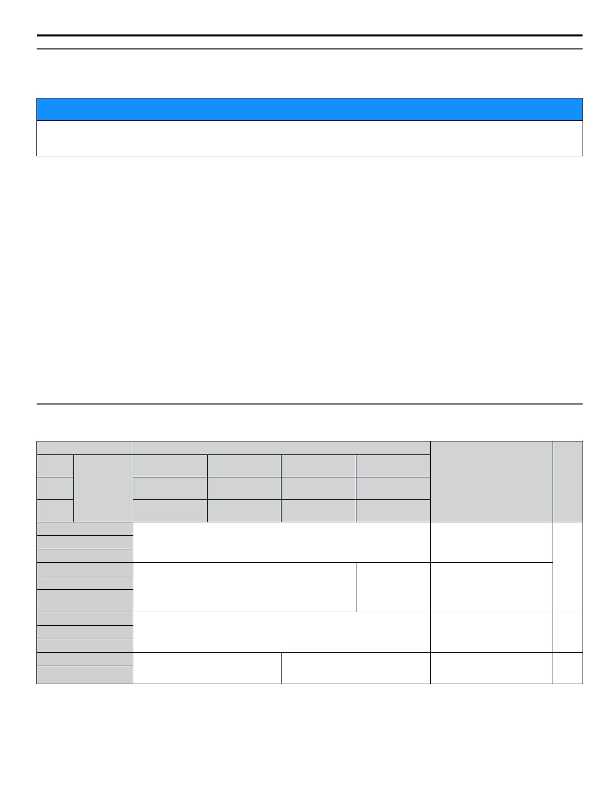
Main Circuit Terminal Functions
Table i.3 Main Circuit Terminal Functions
Terminal Type
Function Page
200 V
Class
Drive Model
2A0004 to
2A0081
2A0110, 2A0138
2A0169 to
2A0415
–
400 V
Class
4A0002 to
4A0044
4A0058, 4A0072
4A0088 to
4A0675
4A0930, 4A1200
600 V
Class
5A0003 to
5A0032
5A0041, 5A0052
5A0062 to
5A0242
–
R/L1
Main circuit power supply input Connects line power to the drive
19
S/L2
T/L3
R1-L11
Not available
Main circuit power
supply input
Connects line power to the drive
Remove the shorting bars
connecting R/L1-R1/L11, S/L2-
S1/L21, T/L3-T1/L31 when
using 12-phase rectification.
S1-L21
T1-L31
U/T1
Drive output Connects to the motor 19V/T2
W/T3
B1
Braking resistor Not available
Available for connecting a
braking resistor or a braking
resistor unit option
–
B2
i.3 Electrical Installation Safety
YASKAWA ELECTRIC TOEP YAIP1U 03B YASKAWA AC Drive – P1000 Safety Precautions
21

 Loading...


