i.6 Parameter Table
This parameter table shows the most important parameters. Default settings are in bold type. Refer to the Technical Manual
for a complete list of parameters.
No. Name Description
A1-03 Initialize Parameters
0: No initialization
1110: User Initialize (parameter values
must be stored using parameter o2-03)
2220: 2-Wire initialization
3330: 3-Wire initialization
5550: oPE04 error reset
8008: Pump
8009: Pump w/ PI
8010: Fan
8011: Fan w/ PI
A1-06 Application Preset
0: General-purpose
8: Pump
9: Pump w/PI
10: Fan
11: Fan w/PI
Note: This parameter is not settable. It is
used as a monitor only.
b1-01
Frequency Reference
Selection 1
0: Digital operator
1: Analog input terminals
2: MEMOBUS/Modbus communications
3: Option PCB
4: Pulse input (terminal RP)
b1-02
Run Command
Selection 1
0: Digital operator
1: Digital input terminals
2: MEMOBUS/Modbus communications
3: Option PCB
b1-03
Stopping Method
Selection
0: Ramp to stop
1: Coast to stop
2: DC Injection Braking to stop
3: Coast with timer
b1-04
Reverse Operation
Selection
0: Reverse enabled.
1: Reverse disabled.
b3-01
Speed Search Selection
at Start
0: Disabled
1: Enabled
b3-24
Speed Search Method
Selection
0: Current Detection
1: Speed Estimation
b8-01
Energy Saving Control
Selection
0: Disabled
1: Enabled
C1-01 Acceleration Time 1
Sets the time to accelerate from 0 to
maximum frequency.
C1-02 Deceleration Time 1
Sets the time to decelerate from maximum
frequency to 0.
C1-03 Acceleration Time 2
Sets the time to accelerate from 0 to
maximum frequency.
C1-04 Deceleration Time 2
Sets the time to decelerate from maximum
frequency to 0.
C1-09 Fast-Stop Time Sets the time for the Fast Stop function.
C1-10
Accel/Decel Time
Setting Units
0: 0.01 s (0.00 to 600.00 s)
1: 0.1 s (0.0 to 6000.0 s)
C1-11
Accel/Decel Time
Switching Frequency
Sets the frequency to switch between accel/
decel time settings
C2-01
S-Curve Characteristic
at Accel Start
S-curve at acceleration start.
C2-02
S-Curve Characteristic
at Accel End
S-curve at acceleration end.
C2-03
S-Curve Characteristic
at Decel Start
S-curve at deceleration start.
C2-04
S-Curve Characteristic
at Decel End
S-curve at deceleration end.
No. Name Description
C6-02
Carrier Frequency
Selection
1: 2.0 kHz
2: 5.0 kHz (4.0 kHz)
3: 8.0 kHz (6.0 kHz)
4: 10.0 kHz (8.0 kHz)
5: 12.5 kHz (10.0 kHz)
6: 15.0 kHz (12.0 kHz)
7: Swing PWM1 (Audible sound 1)
8: Swing PWM2 (Audible sound 2)
9: Swing PWM3 (Audible sound 3)
A: Swing PWM4 (Audible sound 4)
B to E: No setting possible
F: User-defined (determined by C6-03
through C6-05)
d1-01 to
d1-16
Frequency Reference 1
to 16
Sets the frequency reference for the drive.
Setting units are determined by parameter
o1-03.
d1-17
Jog Frequency
Reference
Sets the Jog frequency reference. Setting
units are determined by parameter o1-03.
d2-01
Frequency Reference
Upper Limit
Sets the frequency reference upper limit as
a percentage of the maximum output
frequency.
d2-02
Frequency Reference
Lower Limit
Sets the frequency reference lower limit as
a percentage of the maximum output
frequency.
E1-01 Input Voltage Setting
This parameter must be set to the power
supply voltage.
E1-03 V/f Pattern Selection
0: 50 Hz, Constant torque 1
1: 60 Hz, Constant torque 2
2: 60 Hz, Constant torque 3 (50 Hz base)
3: 72 Hz, Constant torque 4 (60 Hz base)
4: 50 Hz, Variable torque 1
5: 50 Hz, Variable torque 2
6: 60 Hz, Variable torque 1
7: 60 Hz, Variable torque 2
8: 50 Hz, High starting torque 1
9: 50 Hz, High starting torque 2
A: 60 Hz, High starting torque 3
B: 60 Hz, High starting torque 4
C: 90 Hz (60 Hz base)
D: 120 Hz (60 Hz base)
E: 180 Hz (60 Hz base)
F: Custom V/f, E1-04 through E1-13
settings define the V/f pattern
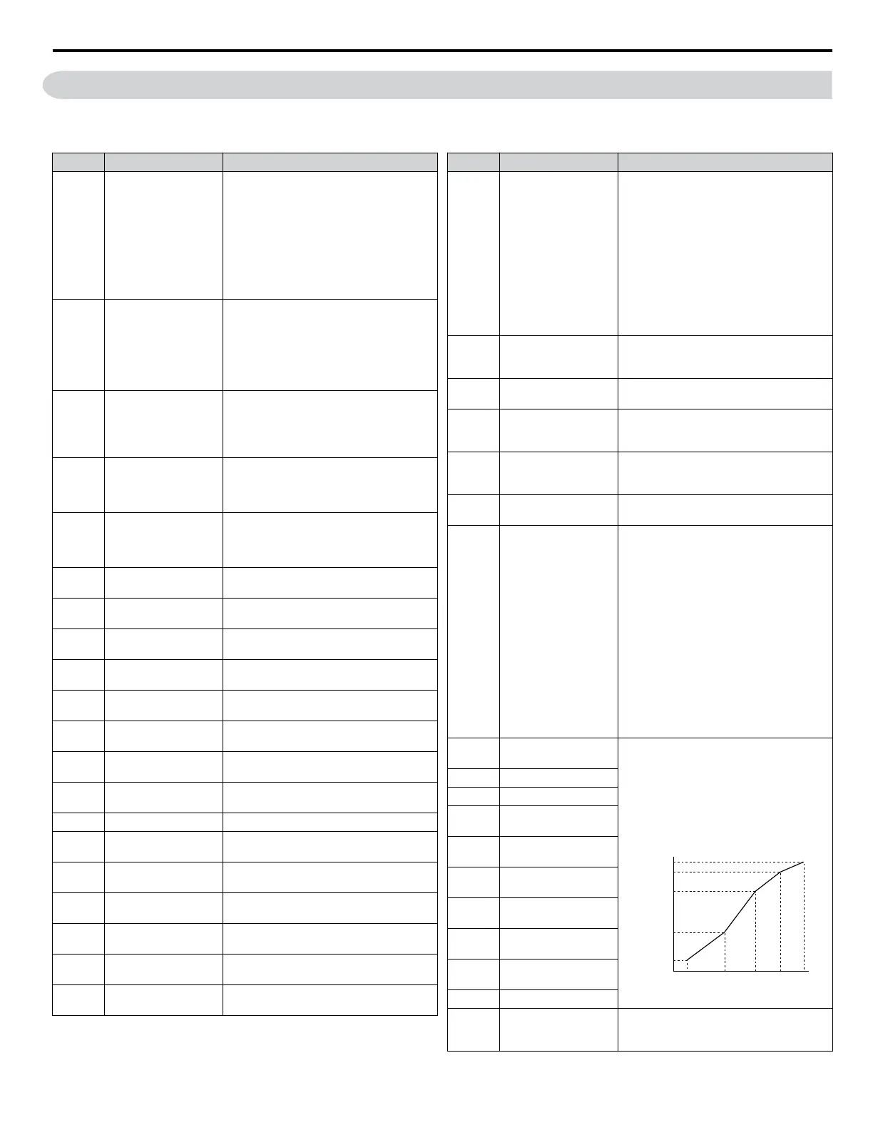
E1-04
Maximum Output
Frequency
These parameters are only applicable when
E1-03 is set to F.
To set linear V/f characteristics, set the
same values for E1-07 and E1-09.
In this case, the setting for E1-08 will be
disregarded. Ensure that the four
frequencies are set according to these rules:
E1-09 ≤ E1-07 < E1-06 ≤ E1-11 ≤ E1-04
Output Voltage (V)
Frequency (Hz)
E1-05
E1-12
E1-13
E1-08
E1-10
E1-09 E1-07 E1-06 E1-11 E1-04
E1-05 Maximum Voltage
E1-06 Base Frequency
E1-07
Middle Output
Frequency
E1-08
Middle Output
Frequency Voltage
E1-09
Minimum Output
Frequency
E1-10
Minimum Output
Frequency Voltage
E1-11
Middle Output
Frequency 2
E1-12
Middle Output
Frequency Voltage 2
E1-13 Base Voltage
E2-01 Motor Rated Current
Sets the motor nameplate full load current
in amps. Automatically set during
Auto-Tuning.
i.6 Parameter Table
YASKAWA ELECTRIC TOEP YAIP1U 03B YASKAWA AC Drive – P1000 Safety Precautions
51

 Loading...


