Drive Model
Nominal
Output Power
HP
AC Drive Input
Amps
MCCB Rating
Amps
<1>
Time Delay Fuse
Rating Amps
<2>
Non-time Delay
Fuse Rating Amps
<3>
Bussman Semi-
conductor Fuse
Rating (Fuse
Ampere)
<4>
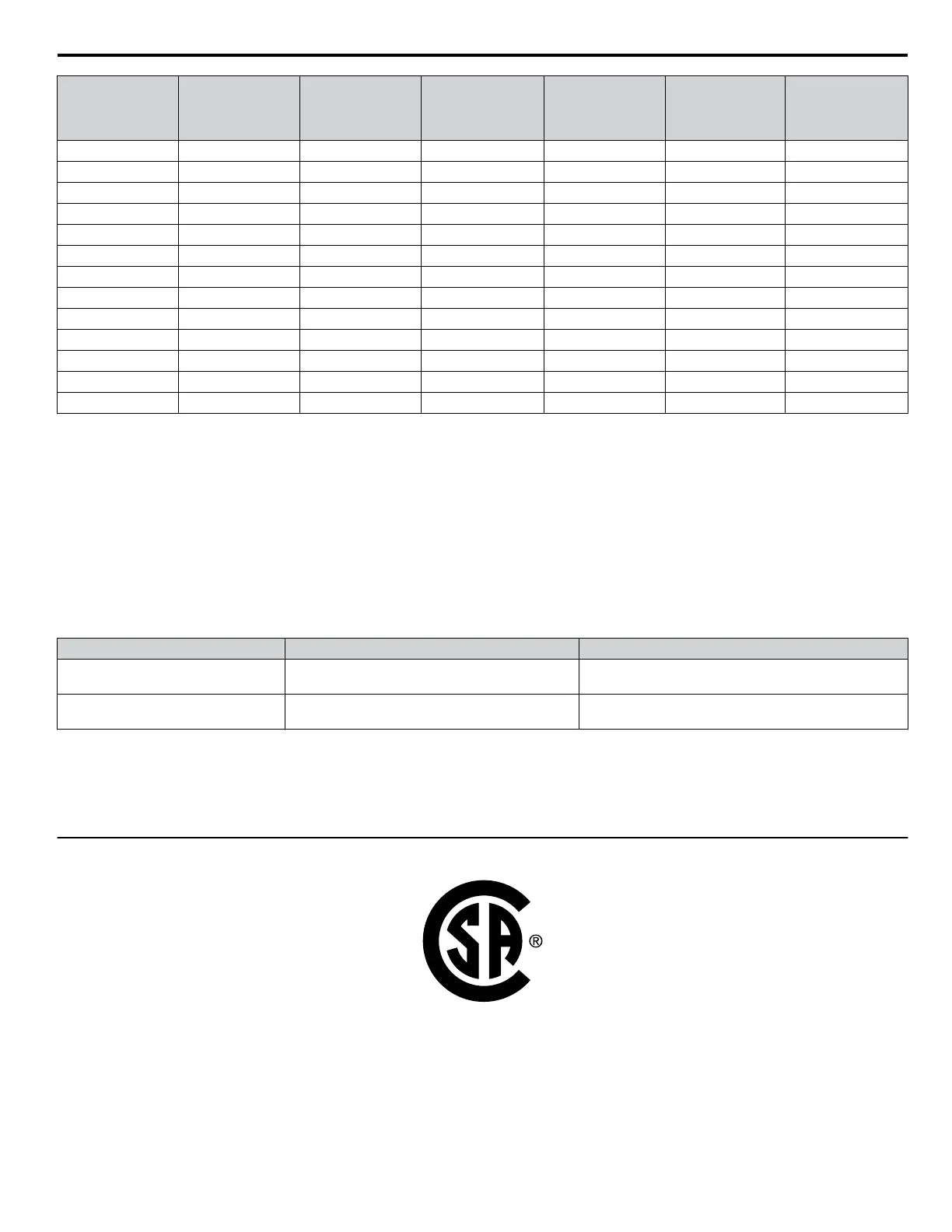
5A0017 15 23 40 40 60 FWP-100B (100)
5A0022 20 31 60 50 90 FWP-100B (100)
5A0027 25 38 75 60 110 FWP-125A (125)
5A0032 30 45 75 75 125 FWP-125A (125)
5A0041 40 44 75 75 125 FWP-175A (175)
5A0052 50 54 100 90 150 FWP-175A (175)
5A0062 60 66 125 110 175 FWP-250A (250)
5A0077 75 80 150 125 225 FWP-250A (250)
5A0099 100 108 175 175 300 FWP-250A (250)
5A0125 125 129 225 225 350 FWP-350A (350)
5A0145 150 158 300 275 450 FWP-350A (350)
5A0192 200 228 400 350 600 FWP-600A (600)
5A0242 250 263 500 450 700 FWP-600A (600)
<1> Maximum MCCB Rating is 15 A, or 200 % of drive input current rating, whichever is larger. MCCB voltage rating must be 600 VAC or greater.
<2> Maximum Time Delay fuse is 175% of drive input current rating. This covers any Class CC, J or T class fuse.
<3> Maximum Non-time Delay fuse is 300% of drive input current rating. This covers any CC, J or T class fuse.
<4> When using semiconductor fuses, Bussman FWH and FWP are required for UL compliance. Select FWH for 200 V Class and 400 V Class models
and FWP fuses for 600 V models.
<5> Class L fuse is also approved for this rating.
n
Low Voltage Wiring for Control Circuit Terminals
Wire low voltage wires with NEC Class 1 circuit conductors. Refer to national state or local codes for wiring. The external
power supply shall be a UL listed Class 2 power supply source or equivalent only.
Table i.22 Control Circuit Terminal Power Supply
Input / Output Terminal Signal Power Supply Specifications
Digital inputs S1 to S8, SC
Use the internal LVLC power supply of the drive. Use class
2 for external power supply.
Analog inputs / outputs +V, A1, A2, A3, AC, AM, FM
Use the internal LVLC power supply of the drive. Use class
2 for external power supply.
n
Drive Short Circuit Rating
The drive is suitable for use on a circuit capable of delivering not more than 100,000 RMS symmetrical Amperes, 240 Vac
maximum (200 V Class), 480 Vac maximum (400 V Class), and 600 Vac maximum (600 V Class) when protected by Factory
recommended branch circuit protection as specified in this document.
u
CSA Standards Compliance
Figure i.26 CSA Mark
i.8 UL and CSA Standards
YASKAWA ELECTRIC TOEP YAIP1U 03B YASKAWA AC Drive – P1000 Safety Precautions
63

 Loading...


