INSTALLATION
INPUT POWER CONNECTION
Check the input voltage, phase, and frequency supplied to
this machine before turning it on. The allowable input voltage
of this machine is 1IOV, which is indicated in the technical
specification section of this manual and on the rating plate of
the machine. Be sure that the machine is grounded.
Make sure the power available at the input connection is ade-
quate for normal operation Ofthe machine
OUTPUT CONNECTIONS
A quick disconnect system using quick cable plugs is used
for the welding cable connections. Refer to the following sec-
tions for more information on connecting the machine for op
eration of flux-core welding, stick welding or TIG welding.
A WARNING
ELECTRIC SHOCK can kill.
• Keep the electrode holder and cable in-
sulation in good condition.
• Do not touch electrically live parts or
electrode with skin or wet clothing.
• Insulate yourself from work and
ground.
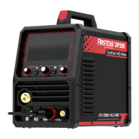
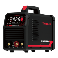
• Turn the input line Switch on the
FLUX-135PRO "off" before connecting
or disconnecting output cables or
other equipment.
FLUX-CORE WELDING
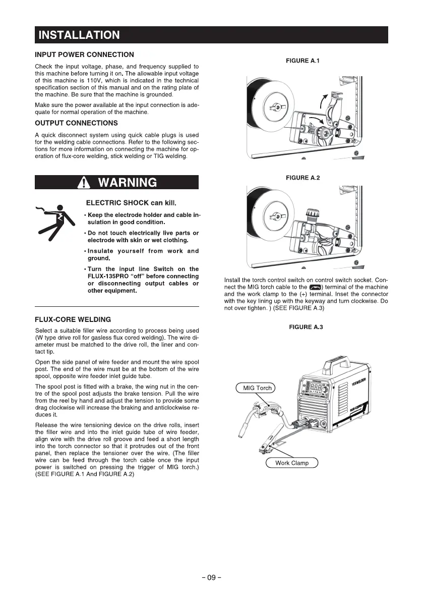
Select a suitable filler wire according to process being used
(W type drive roll for gasless flux cored welding). The wire di-
ameter must be matched to the drive roll, the liner and con-
tact tip
Open the side panel of wire feeder and mount the wire spool
post The end Of the wire must be at the bottom Of the Wlre
spool, opposite wire feeder inlet guide tube
The spool post is fitted with a brake, the wing nut in the cen-
tre of the spool post adjusts the brake tension. Pull the wire
from the reel by hand and adjust the tension to provide some
drag clockwise will increase the braking and anticlockwise re-
duces it
Release the wire tensioning device on the drive rolls, insert
the filler wire and into the inlet guide tube of wire feeder,
align wire with the drive roll groove and feed a short length
into the torch connector so that it protrudes out of the front
panel, then replace the tensioner over the wire. (The filler
wire can be feed through the torch cable once the input
power is switched on pressing the trigger Of MIG torch.)
(SEE FIGURE A 1 And FIGURE A.2)
FIGURE A.I
FIGURE A.2
Install the torch control switch on control switch socket. Con
nect the MIG torch cable to the e) terminal of the machine
and the work clamp to the (+) terminal. Inset the connector
with the key lining up with the kepvay and turn clockwise. Do
not over tighten. ) (SEE FIGURE A.3)
FIGURE A.3
MIG Torch
Work Clamp
- 09 -