IM 01E20D01-01E
8-4
8. EXPLOSION PROTECTED TYPE INSTRUMENT
8.2 FM
(1) Technical Data
*AXF002C – AXF400C
Applicable Standard:
FM3600, FM3610, FM3615,
FM3810, ANSI/NEMA 250
(Integral Flowmeter)
Explosion proof for Class I, Division 1, Groups A,
B, C & D.
Dust-ignition proof for Class II/III, Division1,
Groups E, F & G.
Intrinsically safe (electrodes) for Class I, Division 1,
Groups A, B, C & D.
“SEAL ALL CONDUITS WITHIN 18 INCHES”
“WHEN INSTALLED IN DIV. 2, SEALS NOT
REQUIRED”
Electrode Circuit Um: 250 Vac/dc
Maximum power supply voltage: 250 Vac/130 Vdc
Excitation Circuit: 140V max
Enclosure: NEMA 4X
Temperature Code: T6
Note: Temperature Code T5 to T3 included in the scope of
application and its approval.
Refer to following table;
T0805.EPS
+70°C (+158°F)
+85°C (+185°F)
Temperature
Code
+120°C (+248°F)
Maximum Process
Temperature
–40°C (–40°F)
–40°C (–40°F)
–40°C (–40°F)
–40°C (–40°F)T6
Minimum Process
Temperature
T4
T5
T3 +130°C (+266°F)
Ambient Temp.: –40°C to +60°C (–40°F to +140°F)
(Remote Flowtube)
Explosion proof for Class I, Division 1, Groups A,
B, C & D.
Dust-ignition proof for Class II/III, Division1,
Groups E, F & G.
Intrinsically safe (electrodes) for Class I, Division 1,
Groups A, B, C & D.
“SEAL ALL CONDUITS WITHIN 18 INCHES”
“WHEN INSTALLED IN DIV. 2, SEALS NOT
REQUIRED”
Electrode Circuit Um: 250 Vac/dc
Excitation Circuit: 170V max
Enclosure: NEMA 4X
Temperature Code: T6
Note: Temperature Code T5 to T3 included in the scope of
application and its approval.
Refer to following table;
T0806.EPS
Temperature
Code
Maximum Process
Temperature
–40°C (–40°F)
–40°C (–40°F)
–40°C (–40°F)
–40°C (–40°F)T6
Minimum Process
Temperature
T4
T5
T3
+70°C (+158°F)
+85°C (+185°F)
+120°C (+248°F)
+150°C (+302°F)
Ambient Temp.: –40°C to +60°C (–40°F to +140°F)
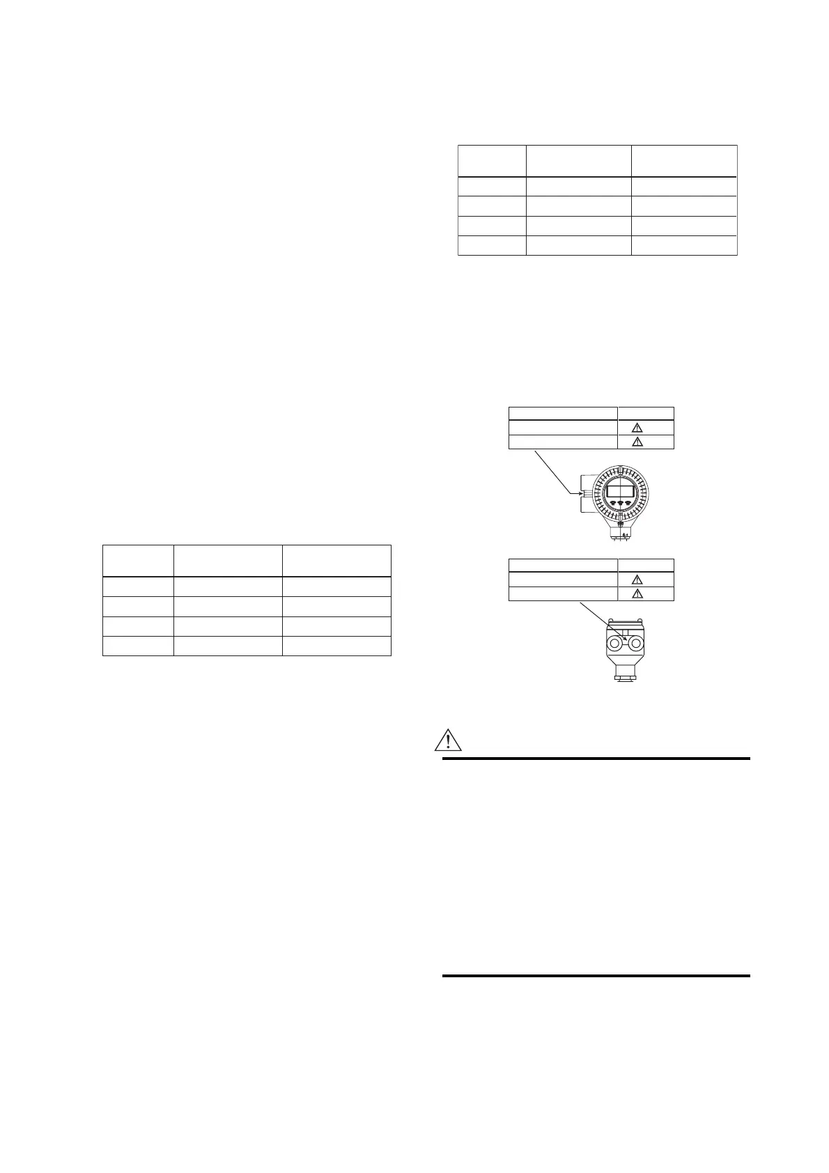
(2) Electrical Connection
The type of electrical connection is stamped near the
electrical connection port according to the following
codes.
Screw Size Marking
ISO M20x1.5 female M
ANSI 1/2NPT female N
F0804.EPS
(Integral Flowmeter)
Screw Size Marking
ISO M20x1.5 female M
ANSI 1/2NPT female N
(Remote Flowtube)
(3) Installation
WARNING
• All wiring shall comply with National Electrical
Code ANSI/NFPA 70 and Local Electrical
Code.
• In hazardous locations, wiring to be in conduit
as shown in Figure 8.2.
• When installed in Division 2, “SEALS NOT
REQUIRED”
• In case the electrodes and/or grounding rings
are made of titanium, the flowtube should be
kept away from impacts and frictions in hazard-
ous locations.
 Loading...
