IM 01E20D01-01E
5-8
5. MAINTENANCE
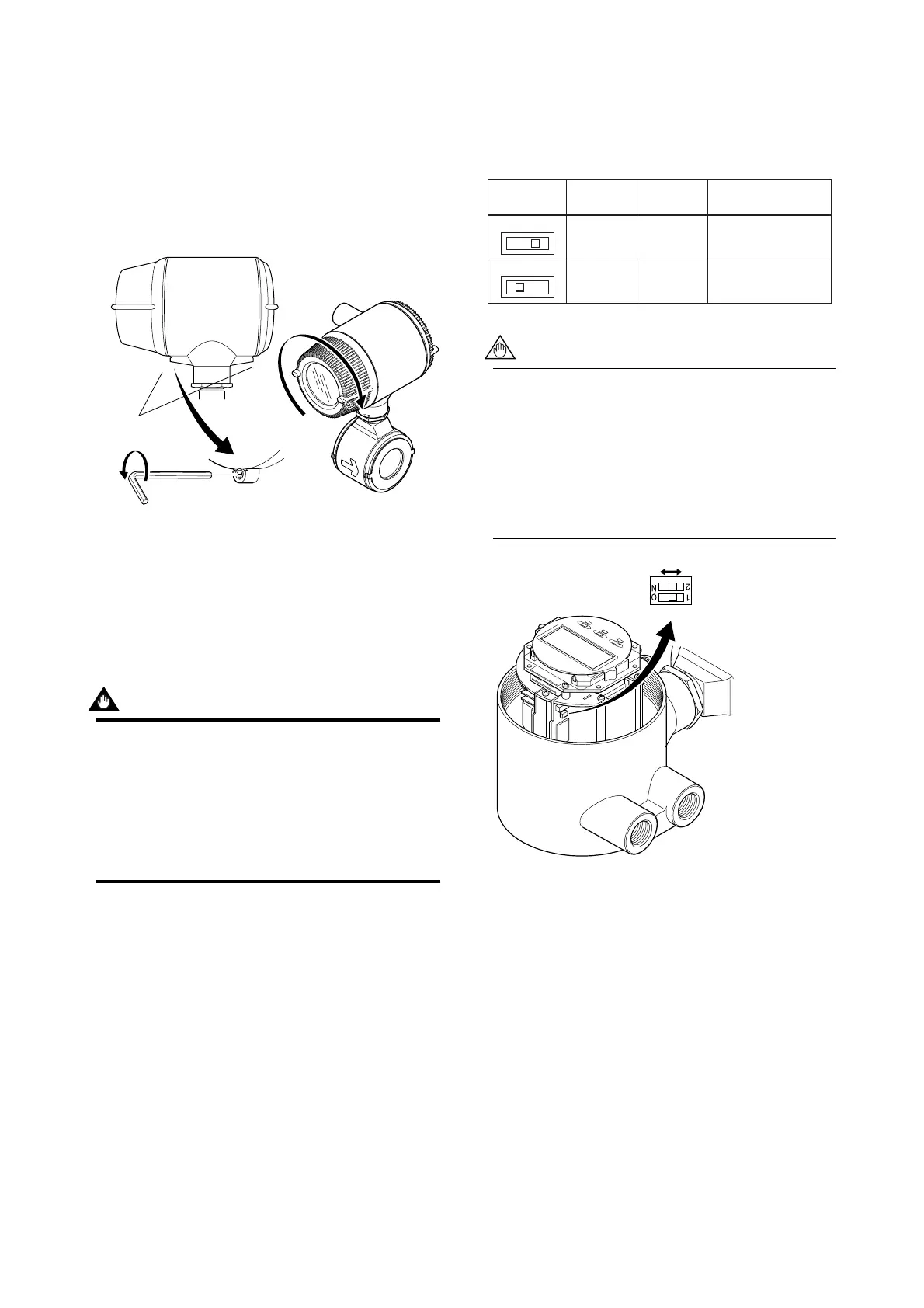
(c) Installing the Cover
(1) Taking care not to entangle the cables, install the
cover to the flowmeter by turning it in the direc-
tion of the arrow as shown below.
(2) Tighten cover locking screw 1 counterclockwise
using a hexagonal wrench (nominal size 3) to lock
the cover.
F0518-2.EPS
Cover locking
screws
Cover locking
screws
1
2
Figure 5.4.3 Installing the Display Cover
5.5 Setting of Switches
(Integral Flowmeter
Only)
IMPORTANT
• Removing and installing cover are necessary
for setting switches. Perform removing and
installing of the cover as described in Subsec-
tion 5.4.2.
• To preserve the safety, do not touch the
electrical circuit and the cables except setting
switches.
5.5.1 Setting of Burnout Switch
The burnout function sets the direction of current
output in situations where the CPU has become
damaged. Upon shipment from the manufacturing
plant, the burnout direction is set to High (i.e., 25 mA);
however, in cases where the optional code C1 has been
specified, the output direction will be set to Low (i.e.,
0 mA).
Modification of the burnout direction must be carried
out using the setting switch from the amplifier’s CPU
board (i.e., Switch 1) (See Figure 5.5.1).
Table 5.5.1 Output Setting Pins for Burnout
T0501.EPS
Position of
Pin
Burnout
Direction
Burnout
Output
Remarks
Low
High
Low High
Low
High
0 mA
25 mA
Set to Low for optional
code C1
Set to High before
shipment
• On the amplifier’s CPU board, the burnout
setting switch (i.e., Switch 1) and the write
protect switch (i.e., Switch 2) are located
adjacent to each other. Accordingly, special
care should be taken when making switch
settings.
• In the case of Fieldbus communication type,
burnout setting switch is not applied.
Switch 1
Low High
Switch 2
Enable Protect
F0520.EPS
2 ← Burnout setting switch
1 ← Write protect setting switch
Figure 5.5.1 Switch Configuration
5.5.2 Setting of Write Protect Switch
By setting the write protect function to “Protect” it is
possible to prevent the overwriting of parameters.
Write protection can be carried out using either the
hardware switch on the CPU board (i.e., Switch 2) (See
Figure 5.5.1) or software parameter settings. If either
of these items is set to “Protect,” the overwriting of
parameters will be prohibited.
 Loading...
