IM 01E20D01-01E
4-6
4. WIRING
Connect the AXF integral flowmeter terminal to
external instruments, giving attention to the following
points. For F
OUNDATION Fieldbus protocol, please refer
to IM 01E20F02-01E. For PROFIBUS PA protocol,
please refer to IM 01E20F12-01E.
䊉 4 to 20 mA DC Current Output
Resistive load max. 750 Ω
Receiver
Instrument
AXF integral flowmeter
l+
l-
F0411.EPS
Communication
Resistive load
BRAIN
HART
250 to 450
Ω
250 to 600
Ω
Figure 4.1.10 4 to 20 mA DC Output Connection
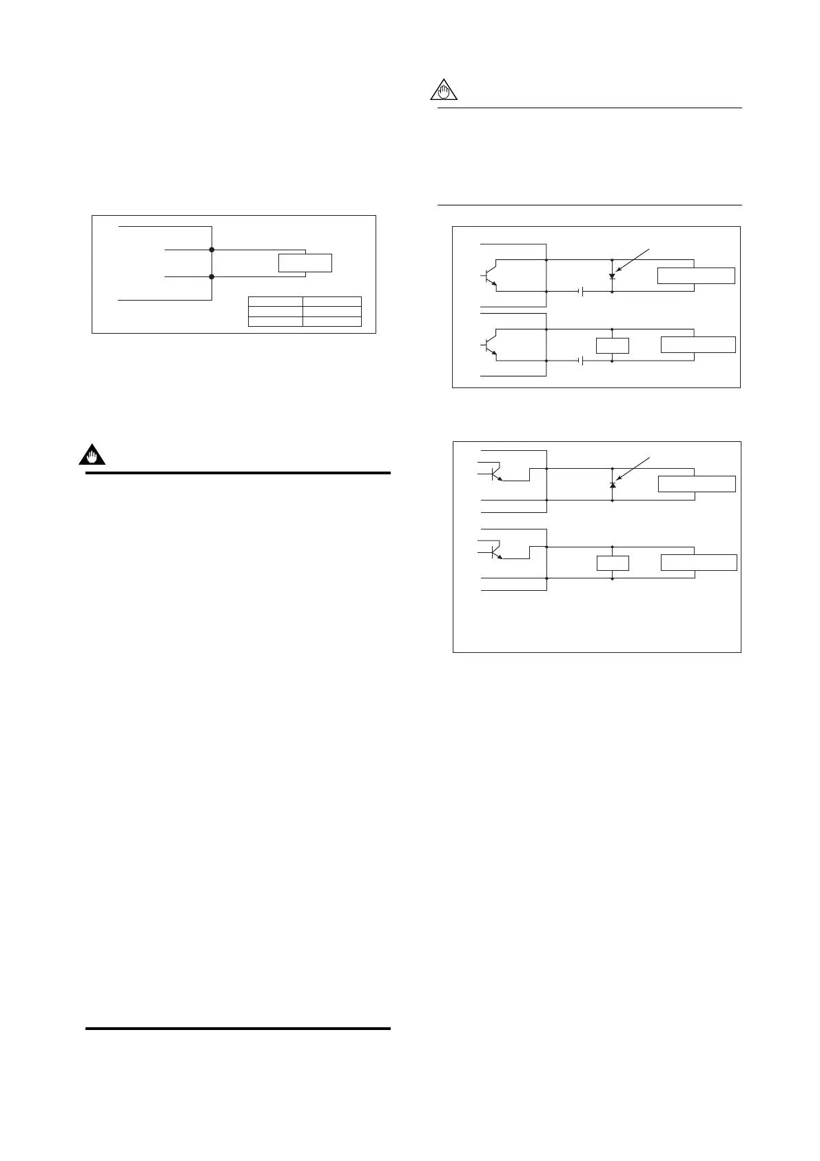
䊉 Pulse Output
IMPORTANT
• As this is a transistor contact (insulated type),
give attention to proper voltage and polarity
when wiring.
• Do not apply a voltage larger than 30V DC or a
current larger than 0.2A in order to prevent
damage to the instrument.
• When input filter constant of the electronic
counter is large in relation to the pulse width,
the signal will decrease and the count will not
be accurate.
• If the input impedance of the electronic counter
is large, an induction noise from the power
supply may result in inaccurate counts. Use a
shield cable or sufficiently reduce the input
impedance of the electronic counter within the
magnetic flowmeter pulse output specification
range.
• The active pulse output (Optional code EM)
cannot be used in conjunction with the standard
pulse output.
• When the active pulse output (Optional code
EM) is selected, do not be short-circuit between
the DO+ and DO– terminals to avoid damaging
the instrument.
• When the active pulse output (Optional code
EM) is selected, the range of pulse rate must
be set to 2 pps maximum.
• To avoid communication (BRAIN/ HART)
failure, it is recommended to use the shield
cable.
For pulse output from the DO terminals, param-
eters must be set. Refer to “Parameter Descrip-
tion” in the user’s manual of the AXF Integral
Flowmeter [Software Edition] (IM 01E20C02-
01E).
F0412.EPS
Mechanical Counter
Electronic Counter
Load
Protective diode
30V DC, 0.2A. max
PULSE OUT
PULSE OUT
AXF integral flowmeter
AXF integral flowmeter
DO+
DO-
DO+
DO-
Figure 4.1.11 Pulse Output Connection
F0413.EPS
Protective diode
PULSE OUT
DO+
DO-
DO+
DO-
Output voltage: 24 V DC 20%
Current: 150 mA or less
Pulse rate: 0.0001 to 2 pps
Pulse width: 20, 33, 50, 100 ms
Mechanical Counter
Electronic Counter
Load
PULSE OUT
AXF integral flowmeter
AXF integral flowmeter
Figure 4.1.12 Active Pulse Output Connection
(Optional code EM)
 Loading...
