<4. Wiring>
45
IM 01E24A01-01EN
4.6 Input and Output
This section provides descriptions of the specicaiton and wiring of the input and output signals.
In accordance with the communication and I/O code specied, the function assigned to each terminal is different. For the
specication and terminal conguration, read Section 4.4 and the applicable general specications as listed in Table 1.1.
For AXFA11, read the applicable user’s manual as listed in Table 1.1.
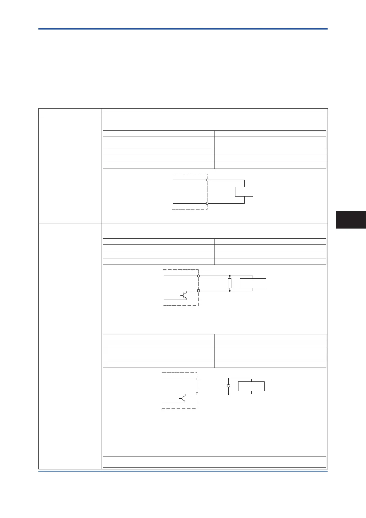
(1) Output Signal
Galvanic isolation:
All circuits for inputs, outputs and power supply are galvanically isolated from each other.
Output signal type Specication
Active current output
[Iout]:
One or two current outputs are available depending on the specication.
Depending on the measured value, the active current output delivers 4 to 20 mA.
Output current 4 to 20 mA DC
Load resistance
750 Ω or less (Integral owmeter or AXW4A),
1 kΩ (AXG1A)
Load resistance for BRAIN communication 250 to 450 Ω
Load resistance for HART communication 230 to 600 Ω
Current output accuracy ±8 μA (±0.05% of span)
F0448.ai
Transmitter
Iout-
Iout+
Receiver
Figure 4.6.1 Connection diagram: Active current output [lout]
Active pulse output
[P/Sout]:
Connection of an electronic counter
Observe that maximum allowable voltage and voltage polarity are correct when wiring.
Load resistance 1 kΩ or more
Internal power supply 24 V DC ±20%
Maximum pulse rate 10,000 pulses/s
Maximum frequency output rate 12,500 Hz
P/Sout-
24 V
Transmitter
0 V
P/Sout+
Electronic
Counter
Load
Resistance
F0449.ai
Figure 4.6.2 Connection diagram: Active pulse output [P/Sout] (Electronic counter)
Connection of an electromechanical counter
Maximum current 150 mA or less
Average current 30 mA or less
Internal power supply 24 V DC ±20%
Maximum pulse rate 2 pulses/s
Pulse width 20, 33, 50, 100 ms
P/Sout-
24 V
Transmitter
0 V
P/Sout+
Electromechanical
Counter
Protective
Diode
F0450.ai
Figure 4.6.3 Connection diagram: Active pulse output [P/Sout] (Electromechanical counter)
When Communication and I/O code DG or JG is specied, upon shipment from the
manufacturing plant, the output is set for electromechanical counter. If the output is set for
electronic counter, the following parameter is change from “For magnetic counter” to “Normal”.
For detailed parameter setting, read the user’s manual of the applicable communication type
as listed in Table 1.1.
Display Menu Path (AXW/AXW4A/AXG1A):
Device setup ►Detailed setup ►Pulse/Status out ►PO2/SO2 ►Active pulse
Wiring
4
 Loading...
