<6. Operation>
58
IM 01E24A01-01EN
NOTE
When the zero adjustment result exceeds dened
value, the warning [092: AZ wam] is indicated.
Zero adjustment can be executed with the following
parameter.
BRAIN Communication:
B50:AUTOZERO EXE
HART Communication Menu Path:
Device root menu ► Basic setup ► Autozero ► Autozero Exe
Modbus Communication:
Register Address: 40361
F
OUNDATION
eldbus Communication:
Device Conguration ► STB ► Device Conguration ►
Maintenance ► Autozero ► Autozero Execute
6.3 Hardware Switch Setting
NOTE
The integral type is explained as an example. Pay same
attention to the AXW4A remote transmitter.
6.3.1 Integral Type and AXW4A Remote
Transmitter
IMPORTANT
•
Removing and installing the cover are necessary for
hardware switches. Perform removing and installing
the cover as described in Section 3.6. When opening
the cover, wait for more than 20 minutes after turning
off the power. This work must be carried out by the
trained personnel having knowledge of safety standard.
•
To preserve the safety, do not touch the electrical circuit
and the cables except the setting switches.
•
When installing the cover, in order to contact the
housing and the cover, be sure to screw it rmly into the
housing without any space between them.
(1) Remove the cover.
(2) While holding the display by hand, loosen the two
mounting screws.
(3) While holding the display by hand (careful for
connecting cable), set the switches. Never remove
connector in this case.
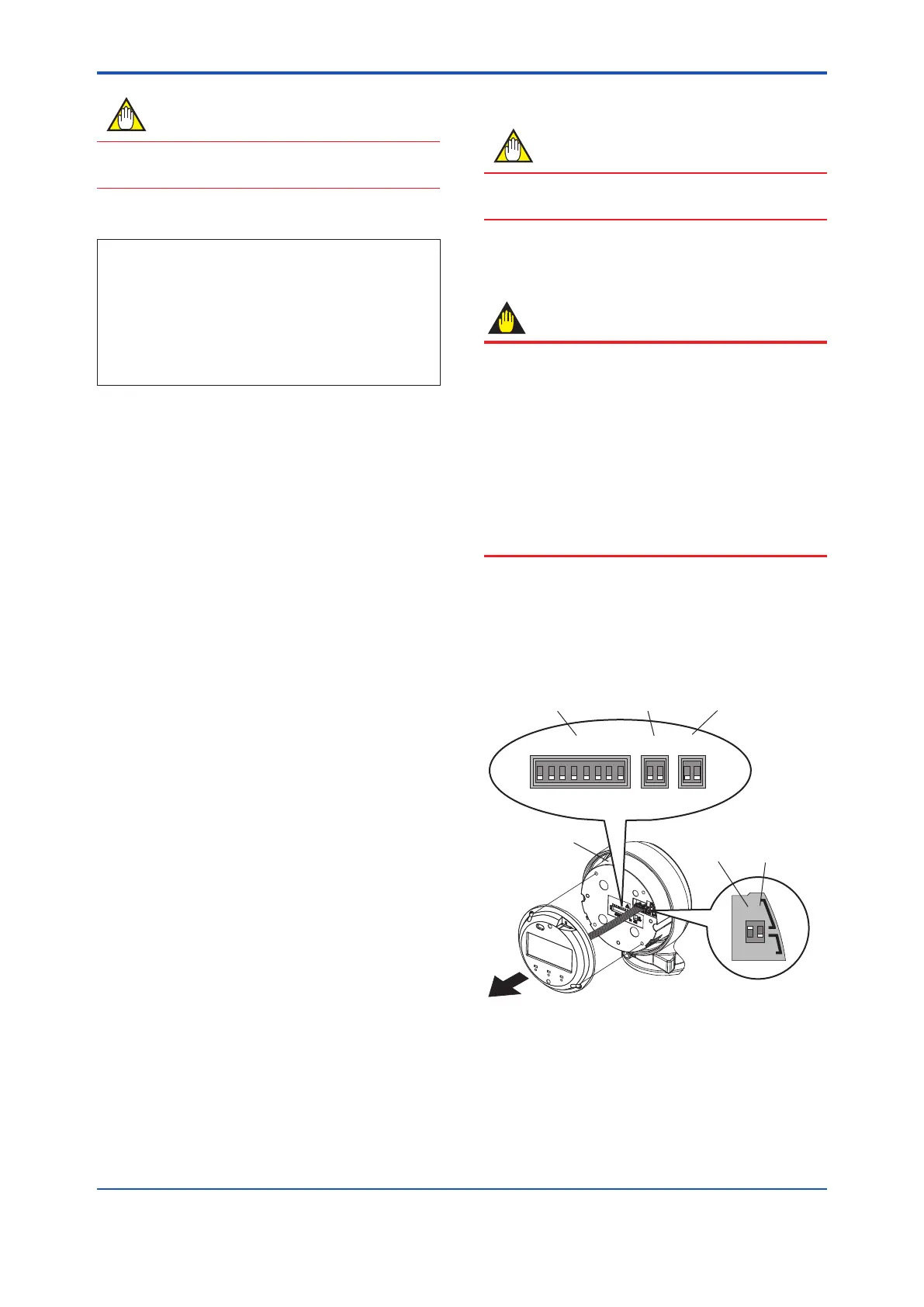
Safety cover
F0610.ai
H
L
1 2
ON
OFF
ON
OFF
SW1
1 21 21 03 25 47 6
0
1
SW3 SW2
ADDRESS
Address switch (ADDRESS)
Pull up and Pull down switch (SW3)
Line termination switch (SW2)
Burnout switch (SW1-1)
*For F
OUNDATION fieldbus communication: Simulation switch
Write protect switch (SW1-2)
*For F
OUNDATION fieldbus communication: Write lock switch
Figure 6.3.1 Hardware switches
 Loading...
