<5. Basic Operating Procedures>
54
IM 01E24A01-01EN
5.6 BRAIN Conguration Tool
The connection of the BRAIN conguration tool
(BRAIN TERMINAL (BT200) or FieldMate (Versatile
Device Management Wizard)) is shown as below.
Read the user’s manual of BT200 (IM 01C00A11-01E)
for the operation, and the user’s manual of BRAIN
communication type as listed in Table 1.1 for the detailed
parameter setting via BRAIN communication.
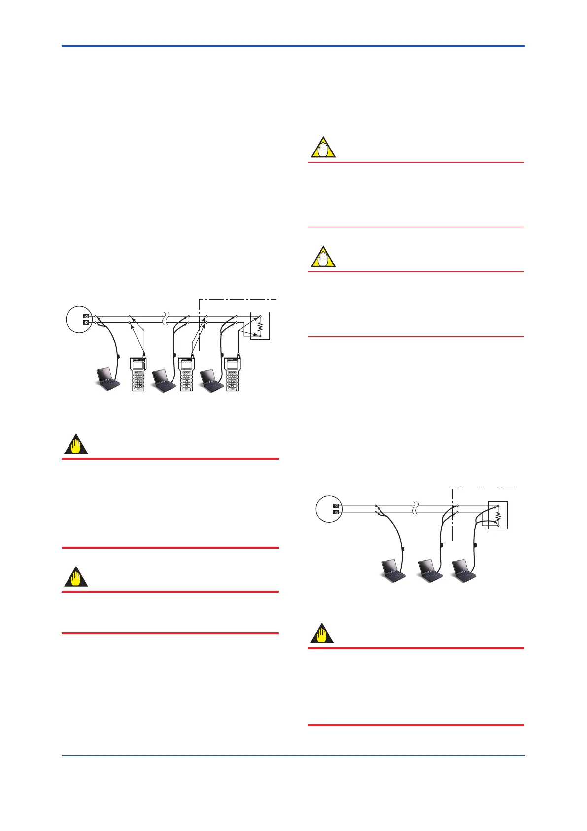
The communication signal is superimposed onto the 4 to
20 mA DC analog signal to be transmitted. The BRAIN
conguration tool can interface with this device from
the control room, this device site, or any other wiring
termination point in the loop, provided there is a minimum
load resistance of 250 Ω between the connection and the
receiving product.
To communicate, it must be connected in parallel with this
device, and the connections must be non-polarized. See
Figure 5.6.
4 to 20 mA DC
Signal
Transmission Line
Distributor
Terminal
Board
BT200
F0529.ai
Iout+
Iout-
USB
FieldMate
Modem
USB
PC/FieldMate
Magnetic Flowmeter
Terminal Box
Relaying
Terminals
Control Room
Load
Resistance
250 to 450 Ω
Figure 5.6 Connecting the BRAIN Conguration Tool
IMPORTANT
Communication signal is superimposed on analog
output signal. It is recommended to set a low-pass
lter (approximately 0.1s) to the receiver in order to
reduce the output effect from communication
signal. Before online-communication, conrm that
communication signal does not give effect on the
upper system.
IMPORTANT
Restrictions exist with regard to the distance over
which communication is possible. Read the general
specications as listed in Table 1.1.
For explosion protection type, the conguration tool
should be connected at the safe site of “no explosive
atmosphere”.
5.7 HART Conguration Tool
The connection of the HART conguration tool
(FieldMate (Versatile Device Management Wizard))
is shown as below. Read the user’s manual of HART
communication type as listed in Table 1.1 for the
detailed parameter setting via HART communication.
NOTE
• For more details regarding the operations of the
HART conguration tool, read the manual of HART
conguration tool.
• When using FieldMate, be sure that the revision is
R3.02.00 or later.
NOTE
Perameters on HART conguration tool are displayed
in English only. Even if any language other than
English is selected as “display language” from display
panel, parameters are displayed in English on HART
conguration tool.
5.7.1 Connections with HART Congura-
tion Tool
The HART conguration tool can interface with this
device from the control room, this device site, or any
other wiring termination point in the loop, provided there
is a minimum load resistance of 230 Ω between the
connection and the receiving product. To communicate,
it must be connected in parallel with this device, and the
connections must be non-polarized.
Read Figure 5.7.
Iout+
Iout-
USB
FieldMate
Modem
USB
PC/FieldMate
Control Room
Magnetic Flowmeter
Terminal Box
Load
Resistance
Relaying
Terminals
Signal
Transmission Line
Terminal
Board
Distributor
Figure 5.7 Connecting the HART Conguration Tool
IMPORTANT
Communication signal is superimposed on analog
output signal. It is recommended to set a low-pass lter
(approximately 0.1s) to the receiver in order to reduce
the output effect from communication signal. Before
online-communication, conrm that communication
signal does not give effect on the upper system.
 Loading...
