20
8.11.2 Continuity Check
<1> Turn the function switch to the Resistance position.
<2> Plug the test leads to terminals.
<3> Use the cursor key to select Continuity check
and then
press the ENTER key to confirm.
[NOTE]
At 1000 Ω range (continuity check), the buzzer turns on for
resistances lower than approx. 30Ω.
8.11.3 Diode Test
<1> Turn the function switch to the Resistance position.
<2> Plug the test leads to terminals.
<3> Use the cursor key to select Diode test and then
press the ENTER key to confirm.
[NOTE]
The “bad” is displayed when measuring a diode conducted at
forward and reverse bias.
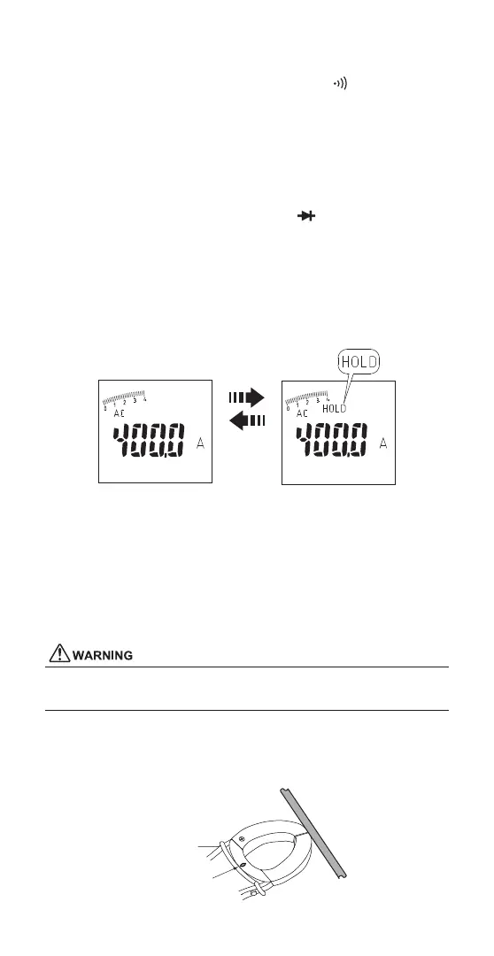
8.12 HOLD
Press the HOLD key (right side) to hold the measured value.
To cancel, press the HOLD key again.
Press
Hold key
[NOTE]
On ACA mode, Press the HOLD key for more than 2 seconds
for zero adjust. See also: Section 8.5 DCA ZERO
Alarm during Hold
The CW10 beeps continuously and the display will flash
if the measured signal is larger than the display reading.
(at Voltage, Current and Active power function)
To cancel, press the HOLD key.
8.13 Voltage Sanse
Even if Voltage Sense LED does not light, do not touch unshielded
wire/cable with bare hand.
In case voltage is detected by the jaw, the red LED lights up.
Ensure that the tip of the jaw touches the object wire.
Take care that the tip of the jaw does not touch other wires.
Use the Voltage Sense LED as an aid only if wire is energized or not.
LED
 Loading...