7
7. Making Basic Measurements
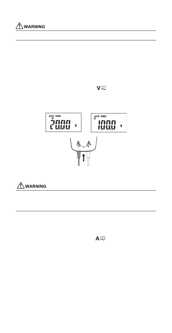
7.1 Measuring Voltage
Do not apply more than 1000 VDC or 1000 Vrms (1414.2 Vpk).
Plug the test leads to the input terminals.
[NOTE]
When connecting the test leads to the circuit under measurement,
connect the black (common) before connecting the red (live);
when removing the test leads, remove the red (live) before
removing the black (common).
Turn the function switch to the Voltage position.
Read the voltage value of display.
On Auto Sense mode, the CW10 automatically detects AC or DC.
Black
Red
7.2 Measuring Current
• Do not apply more than 600 ADC or 600 Arms (848.5 Apk).
• When you measure the current, be sure to remove the test leads
from the instrument.
Squeeze the open/close lever to open the jaws. Insert a wire from the
measurable conductors under the test though the jaws, making sure
the tops of the jaws are tightly shut.
Turn the function switch to the Current
position.
Read the current value of display.
Using Auto Sense mode, the CW10 automatically detects AC or DC.
[NOTE]
• When performing a measurement, hold the instrument so that
the measured conductor cable runs at the center of the clamp.
• Ensure that the orientation of the clamp to the direction of
the conductor wire is correct as shown right.
 Loading...