Making Preparations for Measurements
2.4 Connecting Probes
2-11
IM DLM4038-03EN
2
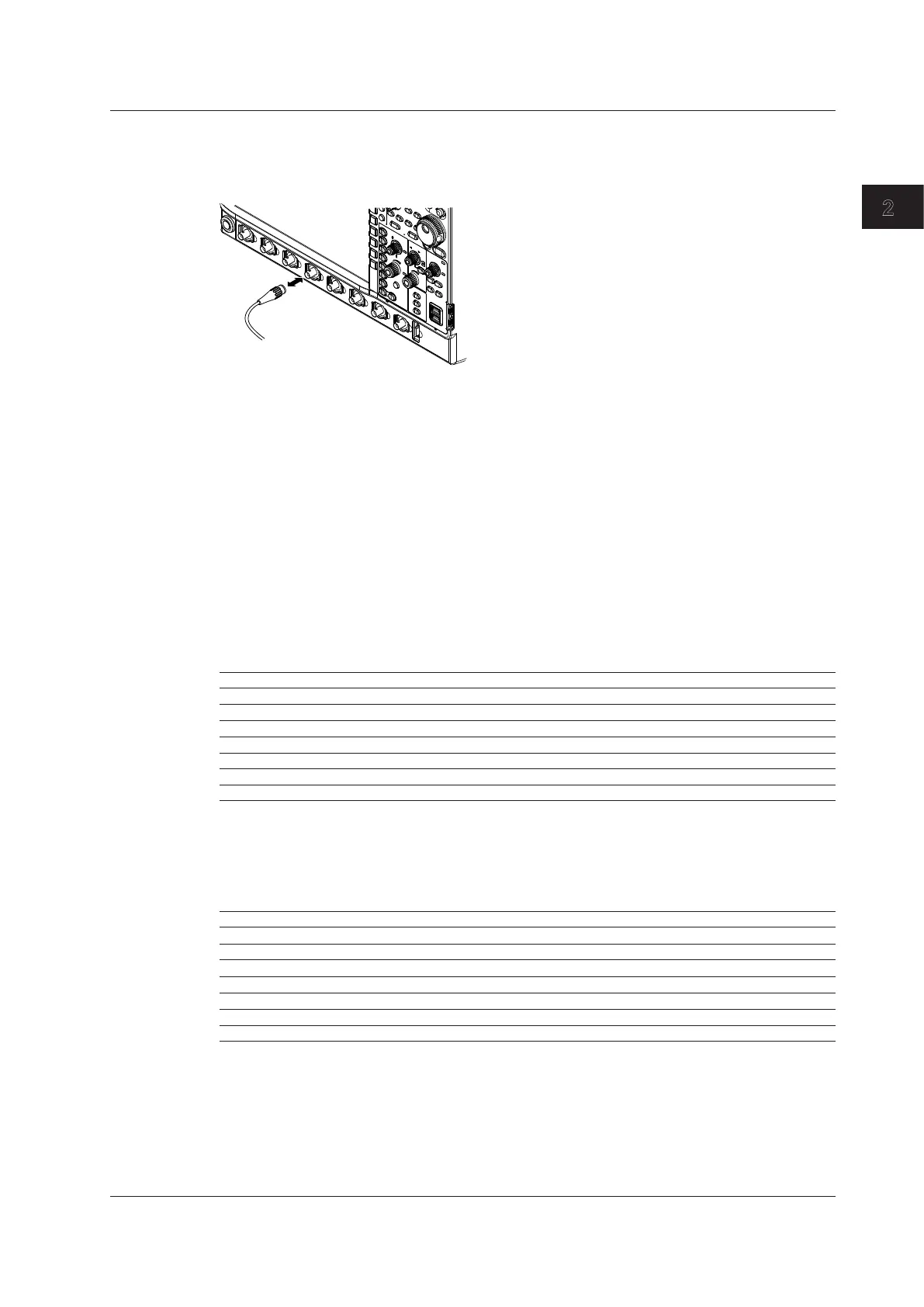
Connecting Probes
Connect probes (or input cables such as BNC cables) to the input terminals on the bottom of the front
panel. The input impedance is 1 MΩ ± 1.0% and approximately 20 pF parallel or 50 Ω ± 1.0%.
Precautions to Be Taken When Connecting Cables
• When connecting a probe to the instrument for the first time, perform phase correction of the probe
as described in section 2.5, “Correcting a Probe Phase.” If you don’t correct the probe phase, the
frequency characteristics will not be flat, and measurements will not be correct. Perform phase
correction on each channel to which a probe is to be connected.
• Please note that if the circuit being measured is directly connected to the instrument without the use
of a probe, correct measurements may not be possible because of the effect of the input impedance
of the instrument.
About Probes
Specifications, after Probe Phase Compensation, of the Standard
Accessory Probe (model 701939)
For details, see the manual that came with the probe.
Item Specification
Length of probe and cable 1.3 m
Input impedance 10 MΩ ± 2%
Input capacitance Approx. 10.5 pF
Attenuation ratio 10:1 ± 2%
Bandwidth DC to 500 MHz (not exceeding –3 dB)
Rise time 700 ps or less (typical*)
Maximum input voltage 600 V (DC + ACpeak) or 424 Vrms
* Typical values represent typical or average values. They are not strictly warranted.
Specifications, after Probe Phase Compensation, of the Optional
Accessory Probe (model 701946)
For details, see the manual that came with the probe.
Item Specification
Length of probe and cable 1.3 m
Input impedance 10 MΩ ± 1%
Input capacitance Approx. 9.5 pF
Attenuation ratio 10:1 ± 2%
Bandwidth DC to 500 MHz (not exceeding –3 dB)
Rise time 700 ps or less (typical*)
Maximum input voltage 400 Vrms
* Typical values represent typical or average values. They are not strictly warranted.

 Loading...


