4-3
IM DLM4038-03EN
4.2 Trigger Output (TRIGGER OUT)
4
Rear Panel Input and Output
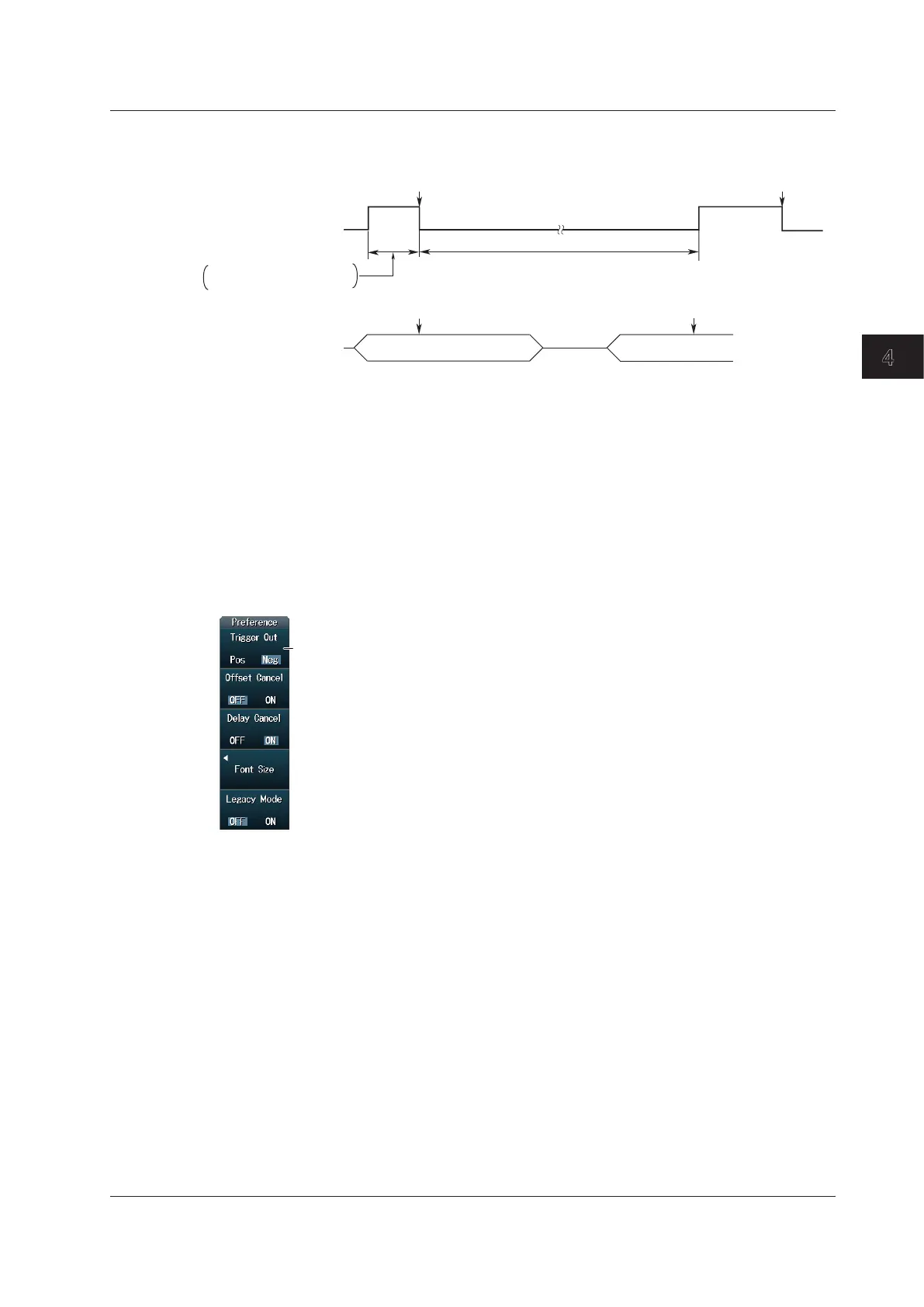
Low Level and High Level Hold Times
High
Low
Trigger output
(negative logic)
*3
(Post-trigger time + internal processing time)
occurrence
occurrence
Pre
Trigger Trigger
Post Post Pre
Pre-trigger time +
internal processing time
*2
*1
*1 High (high level)
3
period: The sum of the pre-trigger time and the internal processing time.
The minimum period is 50 ns.
*2 Low (low level)
3
period: The sum of the post-trigger time and the internal processing time.
The minimum period is 800 ns.
*3 When you select positive logic, the definitions of high and low given here are reversed.
Setting the Output Logic
You can set the output logic for the signal transmitted from the trigger output terminal.
UTILITY Preference Menu
Press UTILITY and then press the Preference soft key to display the following menu.
Set the output logic (Pos: positive logic or Neg: negative logic).

 Loading...


