<3. Installation>
17
IM 01C22A01-01E
IMPORTANT
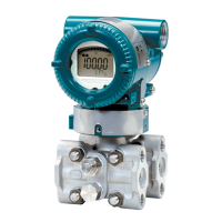
The transmitter should be installed below the high
pressure (HP) process connection to ensure a
positive head pressure of fi ll fl uid. The recommended
height between the HP process connection and the
transmitter is show in the following table. Pay special
attention to vacuum applications.
Model Height (h)
EJA118
600 mm
EJA438W Wetted parts material code S,
T, U, EJA438N
700 mm
EJA438W Wetted parts material code H 1,300 mm
Wetted parts material code
If it can not be installed below the HP process
connection with the recommended height above,
please use the equation below:
h= ×7.5×10
–3
[mm]
(P–P0)×dHg
ds
h: Vertical height between the HP process connection
and the transmitter (mm)
h≤0: Install the transmitter at least h (mm) below
the HP process connection
h>0: Install the transmitter at most h (mm) above
the HP process connection
P: Pressure in the tank (Pa abs)
P0: Minimum working pressure limit of the transmitter
(ambient temperature range: -10 to 50°C)
EJA118
Wetted parts material
code
STHU
P0: Minimum working
pressure limit
3178 3596 6074 4711
EJA438
Wetted parts material
code
ST, UH
P0: Minimum working
pressure limit
5254 6980 13019
ds: Specifi c gravity of fi ll fl uid (at 25°C)
Fill fl uid code A B C, E D
ds: Specifi c gravity
1.07 0.94 1.09
1.90 to
1.92
dHg: Specifi c gravity of the Mercury 13.6 (at 25°C)
Wetted parts material code
Fill fluid code
F0308.ai
P
h
Low
pressure side
0
High
pressure side
(+)
(–)
Figure 3.8 Example of Installation to Tank
(Caution on Installation)
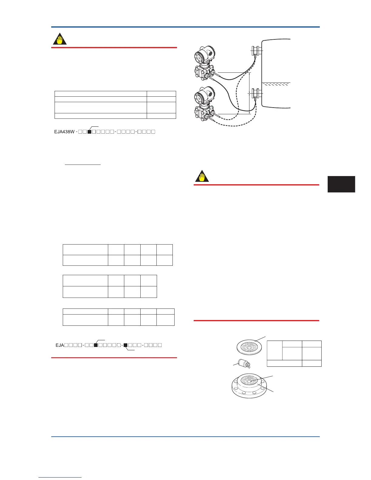
3.4 Affi xing the Tefl on Film
IMPORTANT
The FEP Teflon option includes a teflon film and
fluorinated oil. Before mounting the transmitter to the
process fl ange, affi x the tefl on fi lm as follows:
1) Position the diaphragm so that the diaphragm is in
an upward position.
2) Pour the fl uorinated oil on the diaphragm and
gasket area covering it completely and evenly. Be
careful not to scratch the diaphragm or change the
its shape.
3) Affi x the tefl on fi lm over the diaphragm and gasket
area.
4) Next, carefully inspect the cover and try to identify
any entrapped air between the diaphragm and
the tefl on fi lm. The air must be removed to ensure
accuracy. If air pockets are present, use your
fi ngers to remove the air by starting at the center of
the diaphragm and work your way out.
5) Place the gasket with the tefl on fi lm and affi x to the
process fl ange.
F0309.ai
EJA210A F9347YD
EJA118W
EJA438W
F9347YA
2B
(50A)
F9347XA3B(80A)
Teflon film
PART No.
Diaphragm
Fluorinated oil
[PART No. : F9145YN]
Gasket area
Figure 3.9 Affi xing the Tefl on Film
Installation
3