<5. Wiring>
25
IM 01C22A01-01E
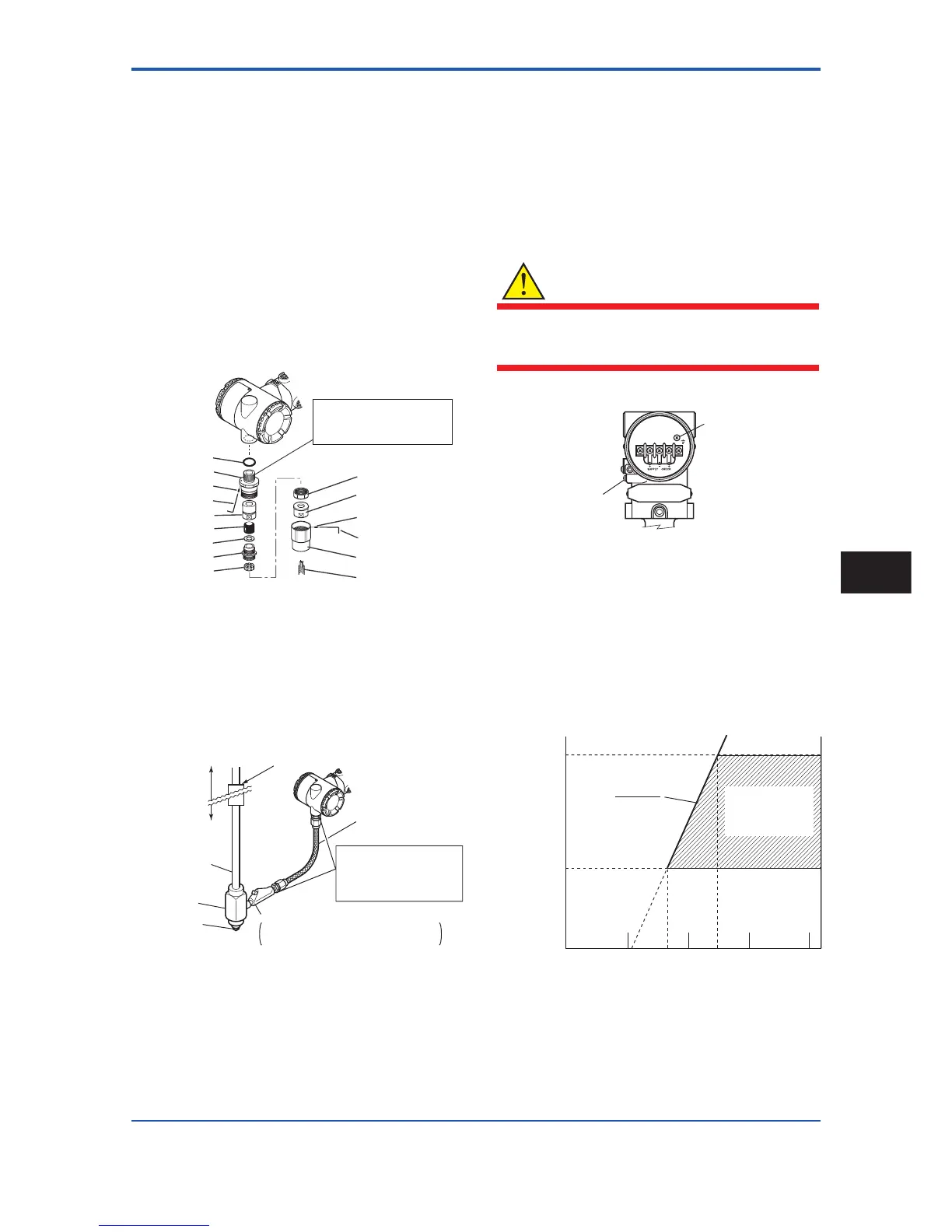
2) Insert the cable through the union cover, the union
coupling, the clamp nut, the clamp ring, the gland,
the washer, the rubber packing, and the packing
box, in that order.
3) Insert the end of the cable into the terminal box.
4) Tighten the union cover to grip the cable. When
tightening the union cover, tighten approximately
one turn past the point where the cable will no
longer move up and down.
Proper tightening is important. If it is too tight, a
circuit break in the cable may occur; if not tight
enough, the fl ameproof effectiveness will be
compromised.
5) Fasten the cable by tightening the clamp nut.
6) Tighten the lock nut on the union cover.
7) Connect the cable wires to each terminal.
O-ring
Adapter body
Lock nut
Wrench
Packing box
Rubber packing
Washer
Gland
Clamp ring
Clamp nut
Union coupling
Lock nut
Wrench
Union cover
Cable
Apply a non-hardnening
sealant to the threads for
waterproofing.
F0508.ai
Figure 5.7 Installing Flameproof Packing Adapter
Flameproof metal conduit wiring
• A seal fi tting must be installed near the terminal box
connection port for a sealed construction.
• Apply a non-hardening sealant to the threads of the
terminal box connection port, fl exible metal conduit
and seal fi tting for waterproofi ng.
F0509.EPS
Non-hazardous area
Hazardous area
Flameproof
heavy-gauge
steel conduit
Tee
Drain plug
Seal fitting
Gas sealing device
Flameproof flexible
metal conduit
Apply a non-hardening
sealant to the threads
of these fittings for
waterproofing
After wiring, impregnate the fitting
with a compound to seal tubing.
Figure 5.8 Typical Wiring Using Flameproof Metal
Conduit
5.4 Grounding
Grounding is always required for the proper operation of
transmitters. Follow the domestic electrical requirements
as regulated in each country. For a transmitter with builtin
lightning protector, grounding should satisfy ground
resistance of 10Ω or less.
Ground terminals are located on the inside and outside of
the terminal box. Either of these terminals may be used.
WARNING
For TIIS fl ameproof type and intrinsically safe,
grounding should satisfy Class D requirements
(grounding resistance, 100Ω or less).
Ground terminal
(Inside)
Ground terminal
(Outside)
Transmitter terminal box
F0610.ai
Figure 5.9 Ground Terminals
5.5 Power Supply Voltage and
Load Resistance
When confi guring the loop, make sure that the external
load resistance is within the range in the fi gure below.
(Note) In case of an intrinsically safe transmitter, external load
resistance includes safety barrier resistance.
600
250
0 10.5 16.4 24.7 42
External
load
resistance
R (Ω)
Power supply voltage E (V DC)
F0511.ai
Communication
applicable range
BRAIN and HART
R=
E–10.5
0.0236
Figure 5.10 Relationship between Power Supply
Voltage and External Load Resistance
Wiring
5