<4. Installing Impulse Piping>
21
IM 01C22A01-01E
(5) Condensate Pots for Steam Flow
Measurement
If the liquid in the impulse piping repeatedly condenses
or vaporizes as a result of changes in the ambient or
process temperature, this will cause a difference in the
fl uid head between the high pressure and low pressure
sides. To prevent measurement errors due to these head
differences, condensate pots are used when measuring
steam fl ow.
(6) Preventing Wind Speed Effects in Very Low
Differential Pressure Measurement
IMPORTANT
When using a differential pressure transmitter to
measure very low pressures (draft pressure), the low
pressure connection port is left open to atmospheric
pressure (the reference pressure).
Any wind around the differential pressure transmitter
will therefore cause errors in the measurement. To
prevent this, it will be necessary either to enclose the
transmitter in a box, or to connect a impulse piping to
the low pressure side and insert its end into a wind
excluding pot (cylindrical with a base plate).
(7) Preventing Freezing
If there is any risk that the process fl uid in the impulse
piping or transmitter could freeze, use a steam jacket or
heater to maintain the temperature of the fl uid.
4.2 Impulse Piping Connection
Examples
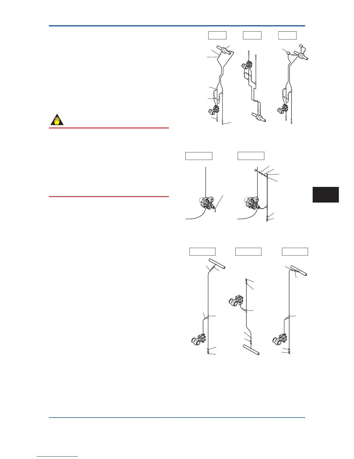
Figure 4.6, 4.7, and 4.8 shows examples of typical
impulse piping connections. Before connecting the
transmitter to the process, study the transmitter
installation location, the process piping layout, and
the characteristics of the process fl uid (corrosiveness,
toxicity, fl ammability, etc.), in order to make appropriate
changes and additions to the connection confi gurations.
Note the following points when referring to these piping
examples.
• If the impulse piping is long, bracing or supports
should be provided to prevent vibration.
• The impulse piping material used must be compatible
with the process pressure, temperature, and other
conditions.
• A variety of process pressure tap valves (main valves)
are available according to the type of connection
(fl anged, screwed, welded), construction (globe, gate,
or ball valve), temperature and pressure. Select the
type of valve most appropriate for the application.
Tee
3-valve
manifold
Drain valve
Orifice
Drain plug
Tap valve
Union
or flange
Liguid
Gas
Condensate pot
Steam
F0406.ai
Figure 4.6 Impulse Piping Connection Examples
(EJA110A)
Pipe (opened to
atmosphere at low
pressure side)
Open Tank
Closed Tank
Tap valve
Union or flange
Vent plug
Tee
Drain valve
Drain plug
F0407.ai
Figure 4.7 Impulse Piping Connection Examples
(EJA210A and EJA220A)
F0408.ai
Liquid
Gas Steam
Union or flange
Tee
Tee
Drain plug
Drain valve
Drain valve
Drain plug
Union or flange
Union or
flange
Union or flange
Tap valve
Tap valve
Tee
Drain valve
Drain plug
Tap valve
Figure 4.8 Impulse Piping Connection Examples
(EJA310A, EJA430A, and EJA440A)
Installing Impulse Piping
4