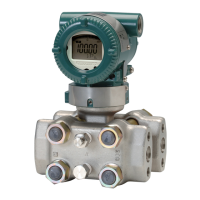
Do you have a question about the YOKOGAWA DPharp Series and is the answer not in the manual?
Guidelines for installing the instrument by qualified personnel.
Instructions for connecting the BT200 handheld terminal.
Explanation of the functions of the BT200 operating keys.
Navigating menu screens using BT200 operating keys.
Procedures for setting various operational parameters.
Procedures for setting various operational parameters.
Process for setting the calibration range and unit.
How to set the lower and upper range values for calibration.
Configuring burnout direction and hardware write protection.
Automatically setting range values with actual input.
Performing zero adjustment using BT200 for pressure.
Performing full sensor trim using zero and span adjustments.
Manually adjusting sensor trim for zero and span errors.
Setting alarm modes and threshold values for pressure.
Identifying problems through connection, operation, and settings checks.
Table summarizing alarm indicators, causes, and countermeasures.
Detailed summary of alarm indicators, causes, and countermeasures.
| Model | DPharp Series |
|---|---|
| Category | Transmitter |
| Stability | ±0.1% of URL per 10 years |
| Accuracy | ±0.04% of span |
| Output Signal | 4-20 mA, HART, BRAIN, FOUNDATION Fieldbus |
| Power Supply | 10.5-55 V DC |
| Process Connection | 1/2" NPT, 1/4" NPT |
| Material | Stainless Steel, Hastelloy |
| Protection Rating | IP66, IP67, NEMA 4X |
| Operating Temperature | -40 to 85°C (-40 to 185°F) |
| Relative Humidity | 0 to 100% RH |
| Response Time | 90 ms |
| Process Temperature Limit | -40 to 120°C (-40 to 248°F) |


