<3. Operation>
3-9
IM 01C25T03-01E
• Example: Change the low cut setting range
from 10% to 20%, and the low
cut mode from LINEAR to ZERO in
the SQUARE ROOT output mode.
FEED NO OK
SET
D11:LOW CUT MODE
ZERO
Use the or key
to select ZERO.
Press the key twice to
enter the setting.
Press the (OK) key.
F0318.ai
FEED NO OK
SET
D10:LOW CUT
20.00 %
ESC
SET
D11:LOW CUT MODE
LINEAR
< LINEAR >
< ZERO >
DATA DIAG PRNT ESC
PARAM
D10:LOW CUT
20.0 %
D11:LOW CUT MODE
ZERO
D15:H/L SWAP
NORMAL
CLR ESC
SET
D10:LOW CUT
10.00 %
+ 20.00
Set 20.
Press the key twice to
enter the setting.
Press the (OK) key.
Next, the [D11: LOW CUT MODE]
setting panel is displayed.
(%)
50
20
0
50 (%)
Output
● Low cut mode “LINEAR”
Input
(%)
50
20
0
50 (%)
● Low cut mode “ZERO”
LOW CUT at 20%
Input
The low cut point has hysteresis so that the output
aroundthepointisbehavedasbelowgure.
<Example>
Output mode: Linear
Low cut mode: Zero
Low cut: 20.00%
F0319.ai
Setting range: 0 to 20%
2% 2%
4mA
Output Low cut point
Input
Hysteresis
fixed at 10%
of the cut point
7.2mA
(20%)
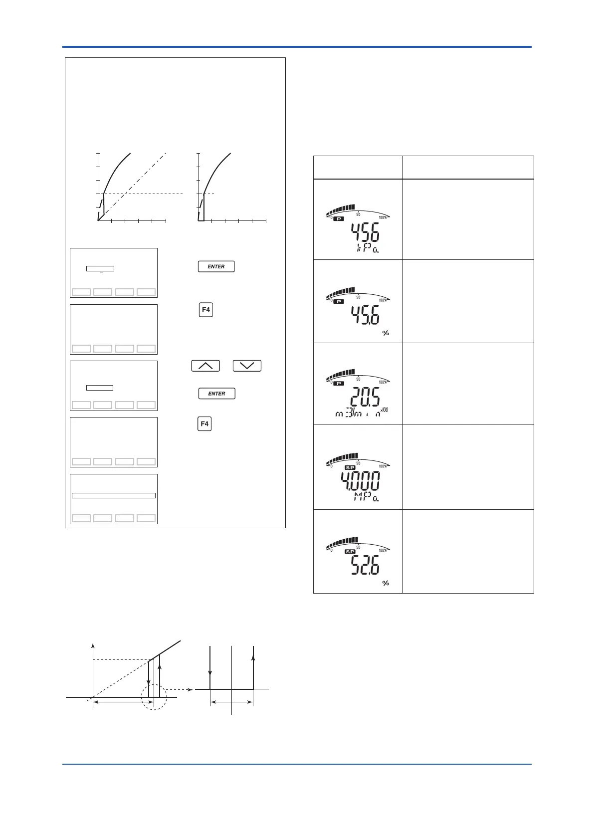
(6) Integral Indicator Scale Setup
Thefollowingvedisplaysareavailableforintegral
indicators: input pressure*
1
, % of range, user
set scale, input static pressure, and % of static
pressure range*
1
. A cycle of up to four displays can
be shown by assigning variables to the parameters
I10 to I13: DISP OUT1 to DISP OUT4.
F0320.ai
Available displays
Input pressure
(PRES)
% of range
(PRES %)
User set scale
(ENGR. PRES)
Input static pressure
(SP)*
1
% of static pressure range
(SP %)*
1
Indicates values of input pressure
with the indication limits -32000 to
32000.
Indicates input pressure in -2.5 to
110% range depending on the
measuring range (C21, C22).
Indicates values depending on the
engineering range (I33, I34) with
the unit (I30).
Indicates input static pressure with
the indication limits -32000 to
32000.
Reference pressure is factory-set
in absolute.
Indicates input static pressure in
-10 to 110% range depending on
the measuring range (D33, D34).
A11:PRES
456 kPa
Description
and related parameters
A10:OUTPUT
45.6 %
A16:ENGR.OUTPUT
20.5 m3/min
A17:ENGR.EXP
×100
A21:SP
4.000 MPa
A20:SP %
52.6 %
*1: Available for differential pressure transmitter.
See (a.) through (d.) for each setting procedure.
 Loading...


