<3. Operation>
3-10
IM 01C25T03-01E
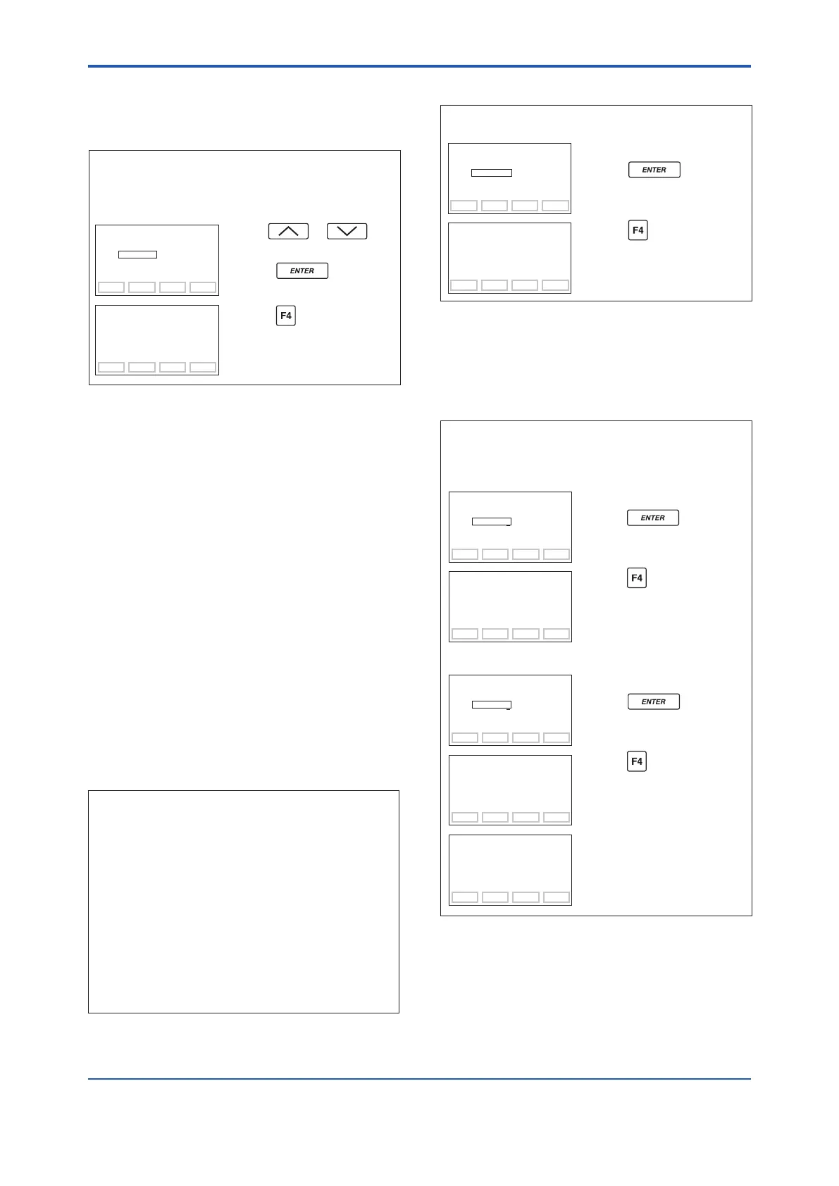
a. Display Selection (I10: DISP OUT1)
Select the variable for the parameter I10: DISP
OUT1 to display on the integral indicator.
• Example: Change the integral indicator scale
from % of range to input pressure
display.
ESC
SET
I10:DISP OUT1
PRES
FEED NO OK
Use the or key
to select PRES.
Press the key twice to
enter the setting.
Press the (OK) key.
F0321.ai
SET
I10:DISP OUT1
PRES %
< PRES >
< PRES % >
< ENGR.PRES >
< SP >
b. Cyclic Display (I11: DISP OUT2, I12: DISP
OUT3, and I13: DISP OUT4)
In addition to the display set at I10: DISP OUT1,
displays can be set at I11: DISP OUT2, I12: DISP
OUT3, and I13: DISP OUT4 for cyclic display in the
order of the parameter number.
c. User Setting of Engineering Unit and Scale
(I30: ENGR.UNIT, I31: EASY EU SET, I33:
ENGR.LRV, and I34: ENGR.URV)
These parameters allow the entry of the
engineering units and scale to be displayed.
The engineering unit can be selected from the
parameter I31: EASY EU SET as listed below.
Alternately, up to eight alphanumerics, spaces, and
a slash “/” can be input on keypad at I30: ENGR.
UNIT;onlyrstsixaredisplayedontheintegral
indicator.
Select the unit from the list of I31: EASY EU SET.
kPa
MPa
mbar
bar
psi
psia
mmH2O
mmHg
mmHgA
mmAq
mmWG
Torr
inH2O
inHg
inHgA
ftH2O
gf/cm2
kgf/cm2
kg/cm2G
kg/cm2A
atm
kg/h
t/h
m3/h
m3/min
l/h
l/min
kl/h
kl/min
Nl/h
Nl/min
Nm3/h
Nm3/min
ACFH
ACFM
SCFH
SCFM
GPH
GPM
m
mm
in
ft
kg/m3
g/cm3
Follow the procedure below to change the settings.
• Example: Set an engineering unit M.
CODE CAPS CLR ESC
SET
I30:ENGR.UNIT
M
FEED NO OK
SET
I30:ENGR.UNIT
M
_
Set M.
Press the key twice to
enter the setting.
Press the (OK) key.
F0322.ai
Note that following symbols are not available.
. – , + * ) ( ’ & % $ # ” !
The transmitter integral indicator shows
“-- -- -- -- -- --” when these are entered.
• Example: Set lower range value (LRV) to –50
and upper range value (URV) to 50.
FEED NO OK
SET
I34:ENGR.URV
50 M
Press the (OK) key.
F0323.ai
DEL CLR ESC
DATA DIAG PRNT ESC
PARAM
I32:ENGR.EXP
---
I33:ENGR.LRV
- 50 M
I34:ENGR.URV
50 M
DEL CLR ESC
SET
I33:ENGR.LRV
0.00 M
- 50
Set –50.
Press the key twice to
enter the setting.
Setting LRV
Setting URV
Set 50.
Press the key twice to
enter the setting.
SET
I34:ENGR.URV
100.00 M
+ 50
FEED NO OK
SET
I33:ENGR.LRV
- 50 M
Press the (OK) key.
 Loading...


