<3. Operation>
3-12
IM 01C25T03-01E
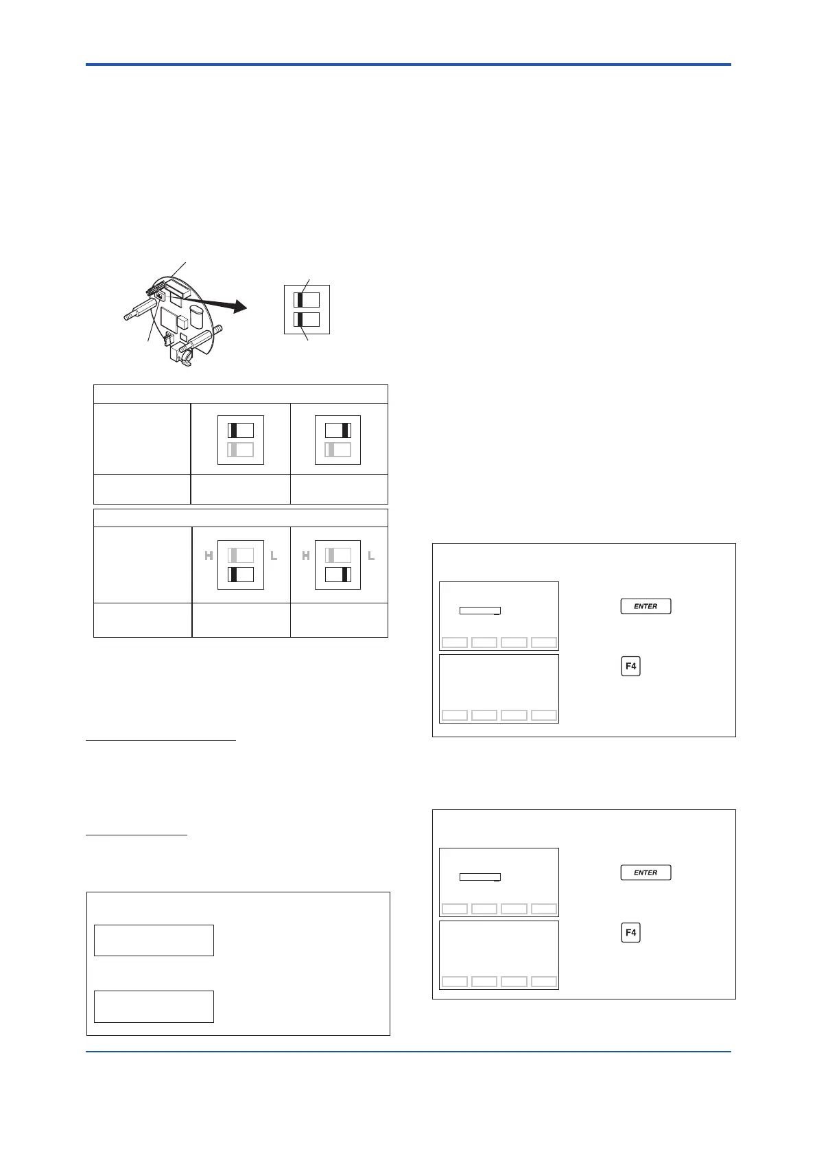
(10) CPU Failure Burnout Direction and
Hardware Write Protect
(D25: BURNOUT)
There are two slide switches on the CPU assembly
board. One sets the burnout direction at CPU
failure, and the other sets a write protection function
which disables parameter changes through
the use of a handheld terminal or some other
communication method.
HIGH LOW
Slide switch
Burnout direction switch
Write protection switch
Write Protection
Switch Position
Burnout Direction
Switch Position
BO H L
WR E D
H L
E D
H L
E D
H L
E D
H L
E D
Hardware write protection switch (WR)
Burnout direction switch (BO)
Burnout Direction
Write Protection
YES
(Write disabled)
NO
(Write enabled)
F0327.ai
The parameter D25: BURNOUT displays the status
of 4-20 mA DC output if a CPU failure occurs. In
case of a failure, communication is disabled.
Standardspecications
The burnout direction switch is set to HIGH. If a
failure occurs, the transmitter outputs a 110% or
higher signal.
Option code /C1
The burnout direction switch is set to LOW. If a
failure occurs, a –5% or lower output is generated.
• Example: Standard specifications
Slide switch position: H
D25: BURNOUT
HIGH
F0328.ai
• Example: Option code /C1
Slide switch position: L
D25: BURNOUT
LOW
(11) Software Write Protect
(D55: WRT PROTECT, D56: WRT
ENABLE, D57: NEW PASSWORD)
Transmittercongureddatacanbesavedbythe
write protect function. Write protect status (D55:
WRT PROTECT) is set from NO to YES when eight
alphanumerics are entered in the parameter D57:
NEW PASSWORD. Accordingly, the transmitter
does not accept any parameter changes. When
the eight alphanumeric password is entered in the
parameter D56: WRT ENABLE, the transmitter
accepts parameter changes during a 10 minute
period.
To cancel the transmitter for the software write
protection completely, use D56: WRT ENABLE to
rstreleasethewriteprotectfunctionandthenenter
eightspacesintheD57:NEWPASSWORDeld.
Thesoftwarewriteprotectiondoesnotaectthe
function of external zero adjustment screw.
To disable the external zero adjustment screw, set
the parameter J15: EXT ZERO ADJ to INHIBIT
before activating the software write protection.
a. Setting Password (D57: NEW PASSWORD)
Enter 1234ABCD.
Then status of parameter D55:
WRT PROTECT becomes YES.
F0329.ai
• Example: Set the password to 1234ABCD.
SET
D57:NEW PASSWORD
1234ABCD
CODE CAPS CLR ESC
SET
D57:NEW PASSWORD
1234ABCD
FEED NO OK
Press the key twice
to enter the setting.
Press the (OK) key.
b. Entering Password to Enable Parameter
Change (D56: WRT ENABLE)
Enter the password.
Parameter changes are available
for 10 minutes.
F0330.ai
• Example: Enter the password of 1234ABCD.
SET
D56:WRT ENABLE
1234ABCD
CODE CAPS CLR ESC
SET
D56:WRT ENABLE
PASS
FEED NO OK
Press the key twice
to enter the setting.
Press the (OK) key.
 Loading...


