<2. Connection>
2-1
IM 01C25T03-01E
2. Connection
The BRAIN communication signal is superimposed
onto the 4 to 20 mA DC analog signal. Since
the modulated wave is a communication signal,
superimposing it on the normal signal will,
from basic principles, cause no error in the DC
component of the analog signal. Thus, monitoring
can be performed via the BT200 while the
transmitter is on-line.
2.1 Connecting the BT200
IMPORTANT
Analog output may change temporally in
connecting with BRAIN terminal due to an initial
currentowedtoit.Topreventcommunication
signalaectingtheuppersystem,itis
recommendedtoinstallalow-passlter
(approximately 0.1s)
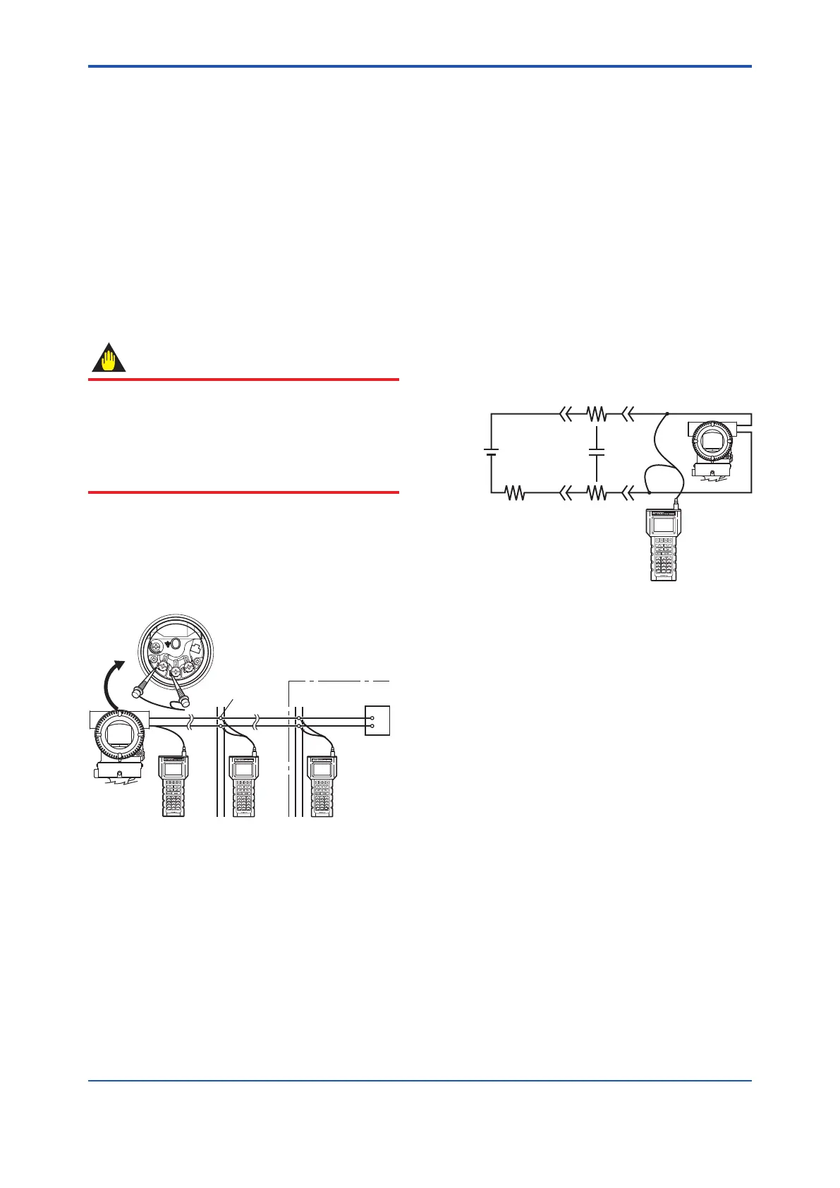
Connection to the transmitter with the BT200
can be made by either connecting to the BT200
connection hooks in the transmitter terminal box or
by connecting to a relaying terminal or a terminal
board.
Relaying
terminals
Distributor
Control room
Terminal board
F0201.ai
Figure 2.1 Connecting the BT200
2.2 Communication Line
Requirements
[Protocolspecication]Yokogawaoriginalprotocol
[Modulation]Burstmodulation
0: 2400Hz
1: Signal without carrier
[Baudrate]1200bps
[Communicationsignal]
hosttodevice:+/-0.5V(loadresistance250Ω)
device to host: +/- 2mA
DPharp
BT200
Cable
resistance Rc
Cable resistance Rc
Load
resistance R
cc
Power
supply
● Loop resistance = R + 2Rc
= 250 to 600 Ω
● Loop capacitance = 0.22 µF max.
F0202.ai
Figure 2.2 Communication Line Requirements
 Loading...


